9 messages on start-up – KROHNE BM 70 A_P EN User Manual
Page 58
Installation and operating instructions BM 70 A/P
Page: 58
11/00
8.9 Messages on start-up
When the BM 70 A/P is powered it will take about 1 minute before the first measured value is displayed (see also Sect. 5.6).
During this time the following flashing messages appear in sequence in the display:
STARTUP - READY - START.
After a short line failure (lasting up to several minutes) it is possible that "LINE INTERRUPT" will be displayed. In such a case,
measurement is continued subsequently taking into account the history prior to the interruption.
8.10 Faults and symptoms during start-up and measurement
•
You will be able to eliminate most of the faults and symptoms likely to occur with the BM 70 A/P by consulting the
following chart.
•
For easy reference, faults and symptoms are divided into the following groups:
Group D
Display
Group A
Signal output
Grop DA
Display and signal output
Group M
markers 1 - 6
6
in the display
Group S
Switching output
•
Please go through these charts before contacting KROHNE Service. Thank you!
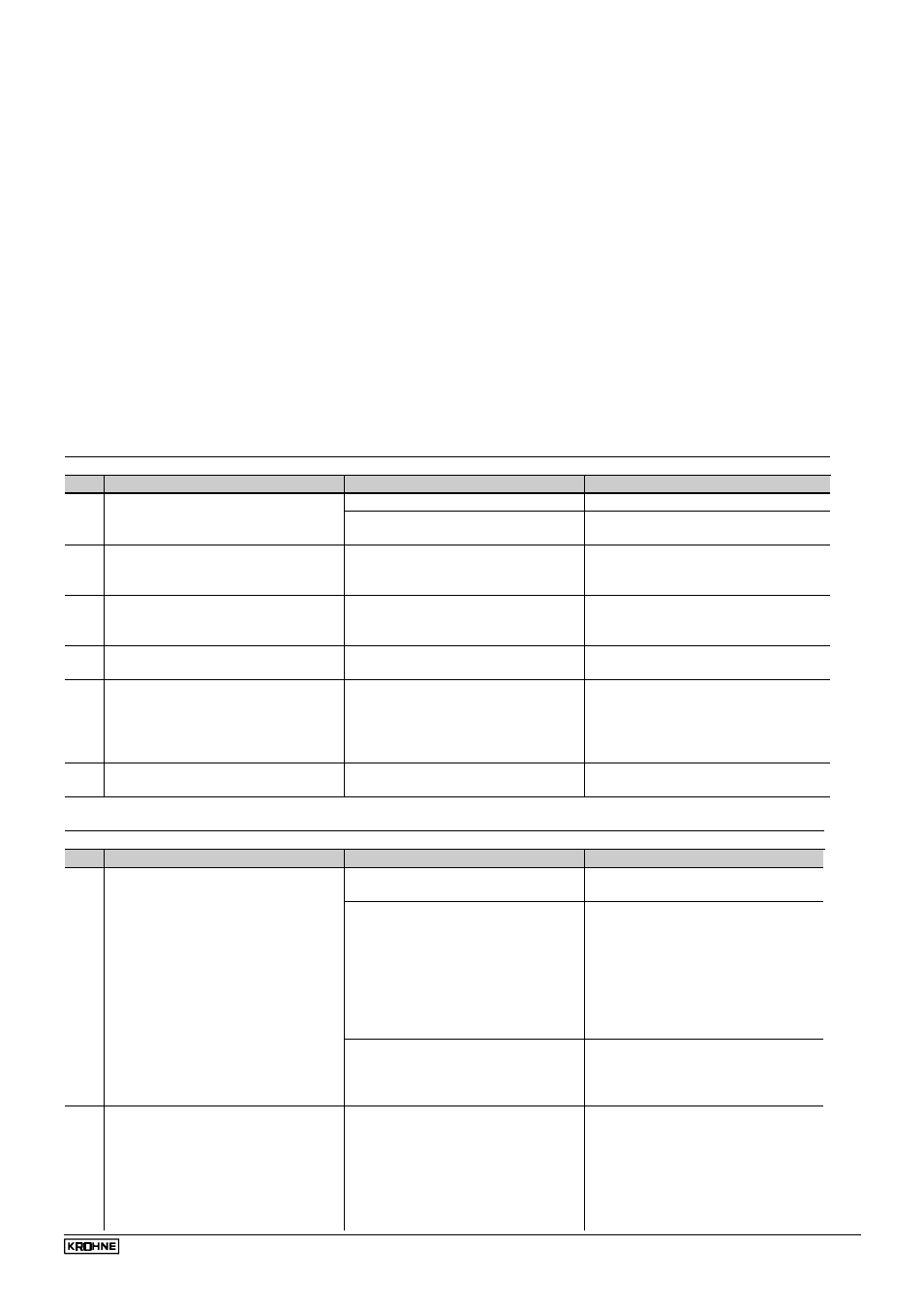
Group D
Display
No.
Fault / Symptom
Cause
Corrective action
D1
Display totally "dead".
Power source switched off.
Switch on power source.
Primary fuse defective.
Change primary fuse as described in
Sect. 9.3.
D2
Display flashes "FATAL ERROR"
shortly after power has been
switched on.
BM 70 A/P is defective.
Replace BM 70 A/P signal converter
(instrument head) as described in
Sect.7.3 .
D3
Display flashes "MIN VALUE" or "
MAX VALUE" when numerical
values are being set.
The set numerical value is outside
the acceptable setting range.
Note MIN. or MAX.VALUE displayed
and set higher or lower numerical
value.
D4
Display shows "START".
Device carries out a hot start after a
parameter change.
Wait until measured value appears.
D5
Display flashes
"SPECT.ERR.".
Newly set operating parameters do
not tally with the stored spectrum
when e.g. the tank height (Fct.
3.1.1) and/or the antenna extension
(Fct. 3.1.4) have been changed.
Record new empty spectrum as
described in Sect. 8.6.12 (Fct. 3.5.2).
D6
Display indicates error message
alternating with the measured value.
An error has occurred.
Note down error messages, eliminate
as described in Sect. 8.8
Group A
Signal output
No.
Fault / Symptom
Cause
Corrective action
A1
Receiver instruments connected to
current output indicate "zero".
Polarity (connection) of receiver
instruments is incorrect.
Connect up properly as described in
Sect. 7.8.
BM 70 A/P current output board or
connected receiver instruments
defective.
Test current output as described in
Sect. 8.7.3.
- All tests OK: Check receiver
instruments and replace if
necessary.
- Test reveals faults: current output
board defective; consult KROHNE
Service or replace BM 70 A/P
signal converter (see Sect. 7.3).
"OFF" (= current output deactivated)
is set under current output I, Fct.
3.3.1, "FUNCTION I".
Depending on the application, set
LEVEL, CONVERSION, DISTANCE
or REFLECTION under Fct. 3.3.1,
see Sect. 8.6.8
A2
2 or 22 mA present at the current
output.
An error has occurred.
Invoke display of error list, see Sect.
8.8. For cause and elimination, see
Sect. 8.8.
If error message not to be displayed
via the current output, set 4-20 mA
without error message, as described
in Sect. 8.6.8 (Fct. 3.3.2).