5 configuration examples – KROHNE BM 70 A_P EN User Manual
Page 42
Installation and operating instructions BM 70 A/P
Page: 42
11/00
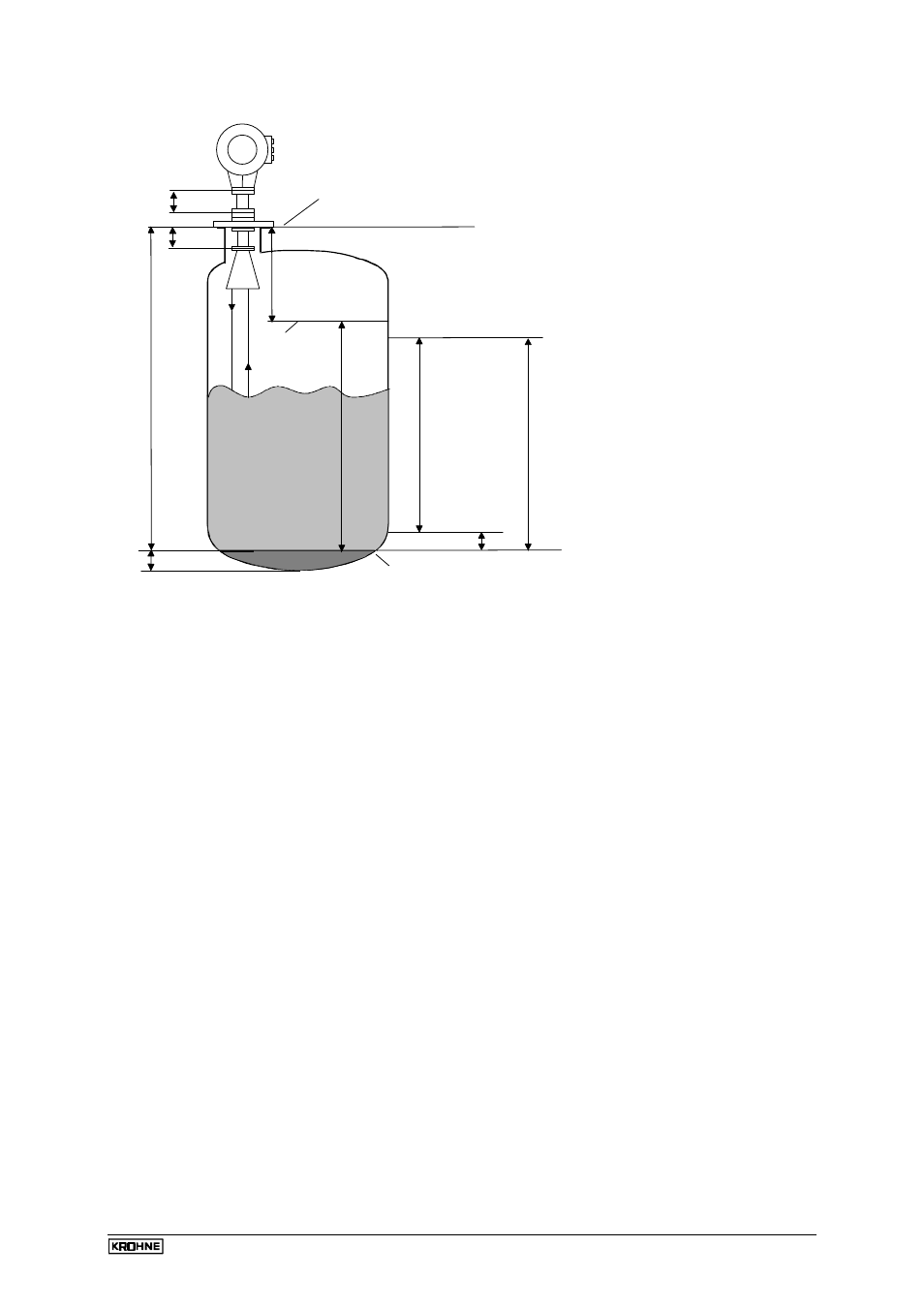
8.5 Configuration examples
8.5.1 Level measurement (example)
Tank height (Fct. 3.1.1):
6.00 m
Antenna extension (Fct. 3.1.4):
0.20 m
Block distance (Fct. 3.1.2):
0.70 m
Response threshold or maximum measurable level = 5.30 m (calculated from lower reference point)
= tank height - block distance
(Fct. 3.1.1) (Fct. 3.1.2)
= 6.00 m - 0.70 m
Current output I
Function I (Fct 3.3.1):
LEVEL
Range I (Fct. 3.3.2):
4 - 20 mA
Scaling 4 mA (Fct. 3.3.3):
0.00 m, equivalent to 4 mA
Scaling 20 mA (Fct. 3.3.4):
5.00 m, equivalent to 20 mA
Switching output
Function S (Fct. 3.6.1):
LEVEL
Type S (Fct. 3.6.2):
LOW (= below threshold)
Threshold (Fct. 3.6.3):
5.00 m
Hysteresis (Fct. 3.6.4)
0.10 m
Display
Function, display (Fct. 3.2.1):
LEVEL
Unit, length (Fct. 3.2.2):
m (meters)
Please note
Display and outputs can also be used for different measured variables,
e.g.: display for conversion, current output I for level, and switching
output S for error messages.
The value for Scaling 20 mA should not be greater than the response
threshold.
Sump
non-
measurable
zone
tank height
(Fct. 3.1.1)
Fct. 3.1.4
upper reference point
(top edge of tank connecting flange)
block distance (Fct. 3.1.2)
response
current output
20
mA
Imax
(Fct. 3.3.4)
4
Imin
(Fct. 3.3.3)
lower reference point
(tank bottom / datum point)
+
+
+
+
+
+
+
+
+
+
+
+
+
+
+
+
+
+
+
+
+
+
+
+
+
+
+
+
+
+
+
+
Fct. 3.1.5
threshold
measuring
mA
range