KROHNE BM 70 A_P EN User Manual
Page 33
Installation and operating instructions BM 70 A/P
Page: 33
11/00
7.8 Electrical connection
The electrical connection for supply power and signal inputs/outputs is made in the terminal compart-
ment (Ex-e) of the signal converter. Observe requirements specified in VDE 165, and consult the
safety advice given in Section 9.4.
In the BM 70 A/P version with intrinsically safe signal output, only certified intrinsically safe
equipment may be connected to the blue terminals, even if the device is not operated in the
hazardous area!
Terminals:
conductor cross-section 0.5 - 2.5 mm² (solid conductor: max. 4 mm²)
PE safety conductor and/or
FE functional ground:
U-clamp terminal (max. 4 mm² conductor cross-section)
(see also terminal assignments below and in Sect. 9.4)
Cablel entries:
3x M25x1.5 (with standard cable gland: cable clamping area = 9-16 mm)
Signal cable shielding:
required for RS 485 line,
recommended for current output when line lengths > 100 m (350 ft)
"Ex" equipotential bonding:
U-clamp terminal (max. 4 mm² conductor cross-section) on "neck" of
signal converter
Rated temperature of power cables:
Version
Max. flange
temperature
Rated
temperature of
power cables
w/o high temperature
≤
100°C/212°F
70°C/158°F
distance piece
> 100°C/212°F
80°C/176°F
with high temperature
≤
200°C/392°F
70°C/158°F
distance piece
> 200°C/392°F
80°C/176°F
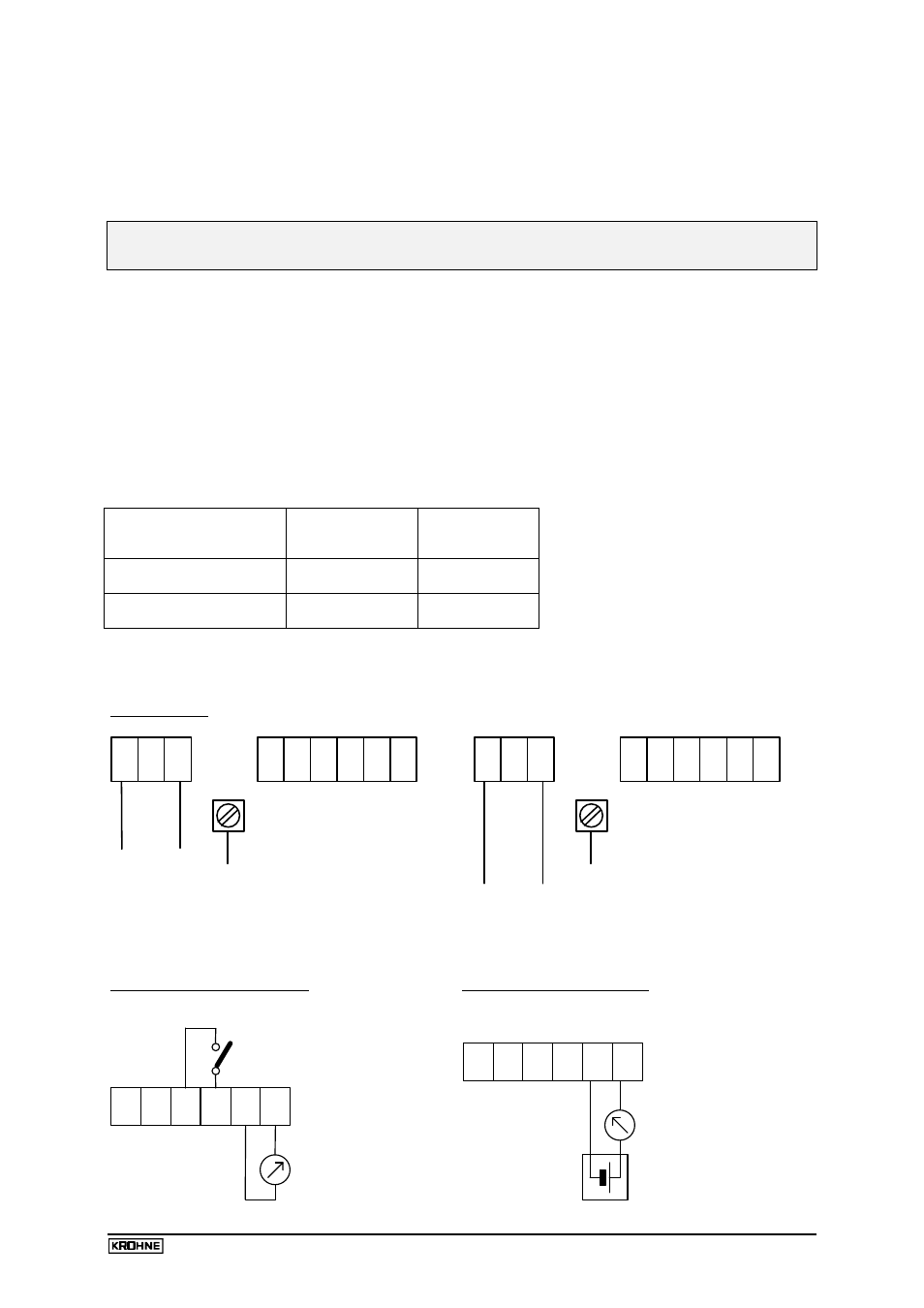
Terminal assignment
Supply power:
N
L
PE
~
~
N
L
Inputs/Outputs
1
2
+(-)
-(+)
24V DC
24V AC
FE
~
~
Inputs/Outputs
Connections for 115/230 V AC
Connections for 24 V DC/AC (any polarity)
Connection of an FE functional ground is not mandatory.
Current output HART
®
, Ex e:
Ex-i current output HART
®
:
32 31
-
+
42 41
Current
output
Switching output
max. 100mA/30V DCAC
Digital
input
82 81
- +
- +
5...28V=
4-20mA
max.500
Ω
32 31
-
Ex-i (IS)
+
+
supply unit
+
-
U max.= 30V
Current
output
4-20mA
U min.= 8V