6 operating conditions – KROHNE BM 70 A_P EN User Manual
Page 17
Installation and operating instructions BM 70 A/P
Page: 17
11/00
6 Operating conditions
Hazardous-duty systems
•
The BM 70 A/P is certified in conformity with European Standard (ATEX) for use in Zone 0, 1 and
2 hazardous locations.
•
The BM 70 A/P also has FM Approval (Factory Mutual) for CLASS I, DIV 1, GROUPS B,C,D;
CLASS II/III, DIV 1, GROUPS E,F,G.
•
Attention is drawn to the information given on the nameplate and the specifications in the
approval certificates.
•
When carrying out installation, dismantling work or making electrical connections in the
hazardous area, be sure to observe the pertinent wiring and installation regulations, e.g. as
specified in VDE 0165.
•
Within the scope of routine checks required to be carried out on systems operated in hazardous
areas (maintaining the system in good working order), the "flameproof enclosure" (large cover on
signal converter) should also be visually inspected for signs of external damage and corrosion.
•
Before opening the "flameproof enclosure" (e.g. to inspect the inside or for repair purposes)
make absolutely certain in the hazardous location:
- that the BM 70 A/P Level-Radar is disconnected from voltage, and then allow the prescribed
waiting time of 22 minutes to elapse first,
- and that there is no explosion hazard (gas-free certificate!).
Safety
•
Operator control via the keys: on electrical safety grounds, operator control of the keys (below
the display, with the housing open) may only be carried out by specialist personnel for service and
repair work, on no account, however, when there is risk of explosion!
•
Surface temperature: the housing of the signal converter can, in extreme ambient conditions,
assume temperatures of more than 70°C (158°F)!
6.1 Installation conditions
Refer to Section 7.5 for selection of the optimum antenna type
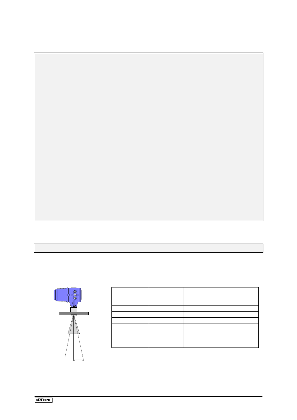
6.1.1 Transmission angle
The transmission angle is defined as the angle
α
to the vertical, in which the power density of the
radar waves assumes half the value of the maximum power density (half-power beamwidth):
α
α
s
Antenna Type
Diameter
mm (inches)
Trans-
mission
angle
α
Lobe expansion s per
metre distance
Type 4
200 (7.87)
6°
10 cm (3.94”)
Type 3
140 (5.51)
8°
14 cm (5.51”)
Type 2 *
100 (3.94)
12° *
22 cm (8.67”)
Type 1 *
80 (3.15)
16° *
30 cm (11.8”)
Wave-Stick
25 (0.98)
9°
16 cm (6.3”)
Wave-Guide /
stilling well
25-200
(0.98-7.87)
Propagation only inside the
stilling well
* Should only be used in stilling wells; the transmission angle given
applies to line-of-sight propagation, i.e. without stilling well.