Hired-Hand Emergency Back-Up and Alarms: Secondary Sensing System Expansion User Manual
Page 24
Manual No. 4801-3001 Rev 7-08
Secondary Sensing System Expansion
24 of 46
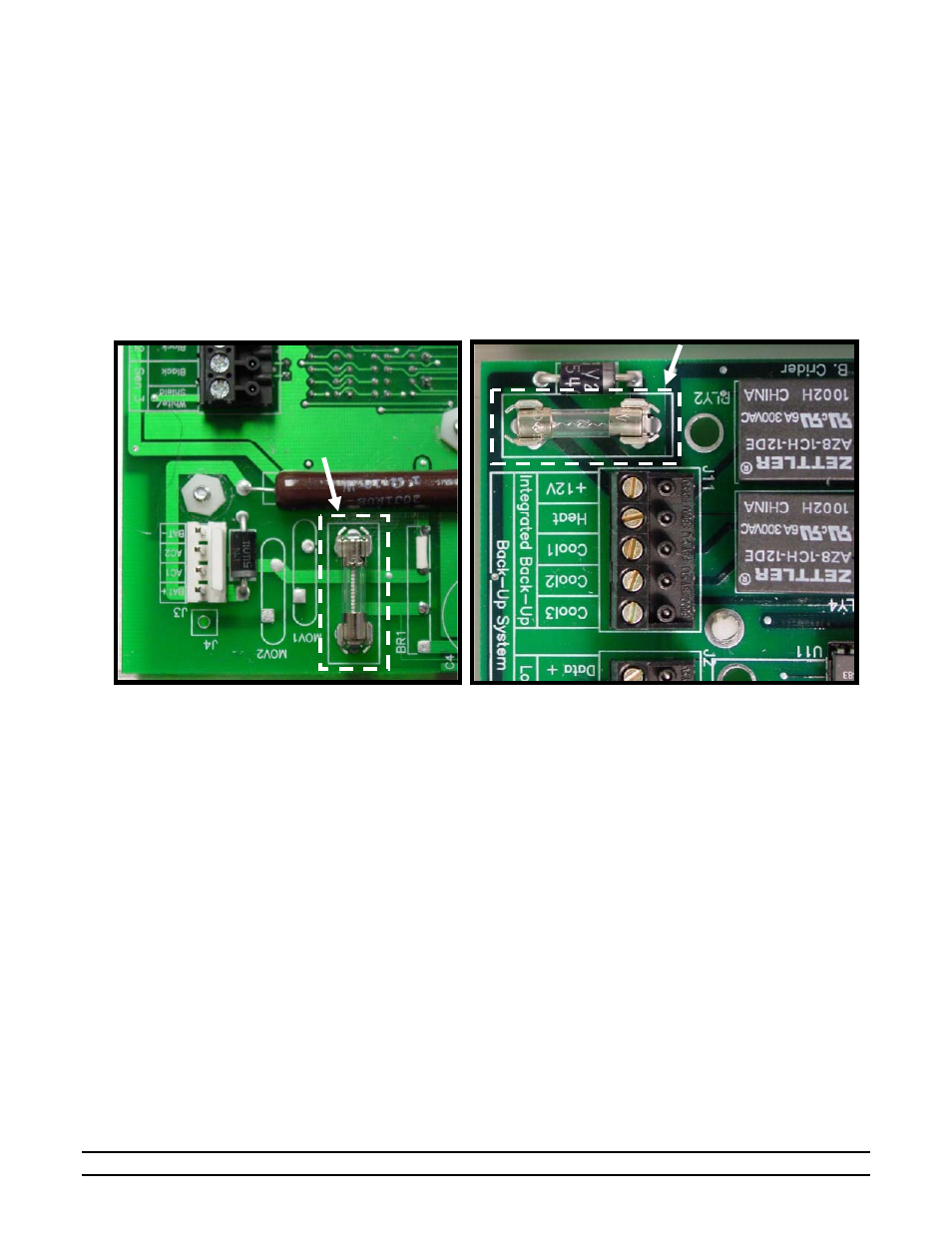
PCB179 DC Primary Power Fuse (F1, 3 Amp Slow-Blow)
The PCB179 DC Primary Power Fuse F1 is located on the PCB179 circuit board near J3. This fuse helps
to provide protection between the power supply board PCB184 and the PCB179 primary DC power input.
This fuse is not connected to the backup battery. Check this fuse when the PCB179 front panel displays are
operating but relying on the backup battery for DC power OR if the PCB179 front panel displays are OFF.
Back-Up Relay Fuse (F2, 3 Amp Slow-Blow)
The Back-Up Relay Fuse is located on the PCB179 circuit board near RLY2. This fuse helps to provide
protection between the S
3
circuitry and the EV-3000/3001. If all AC power is turned OFF or unplugged at
the electrical outlet AND the externally powered controls are also lacking power, the 3 Amp slow-blow fuse
F2 should be checked for a blown fuse.
Fuse Replacement
To replace either fuse, disconnect AC power, disconnect the positive (+) battery terminal from the battery,
and carefully replace the blown fuse with the correctly sized replacement fuse. Reconnect the positive (+)
battery terminal to the battery, plug the male plug end of the AC power cord to the electrical outlet, and
verify that power and functional operation has been restored.
10.5 Temperature Sensors Disconnected
If the temperature Sensors become disconnected or damaged, the Display Indicator for that sensor will show
a line of bars (- - -). This problem should be corrected before any attempt to calibrate the sensor is made.
10.6 Temperature Sensors Out of Calibration
If the operator believes that the temperature sensors are not reading correctly, the following steps should be
followed: Obtain a thermometer that is known to be accurate. Place this thermometer next to the temperature
sensor for at least 10 minutes. Insure that there are no strong breezes or winds blowing on the thermometer
and the sensor being calibrated. Note the temperature from the thermometer and use this reading to calibrate
the sensor. Refer to Section 11.3 for Sensor Recommendations.
10.7 Trouble-Shooting the Auxiliaries
The auxiliary inputs must always form a closed loop circuit. If the loop is ever open, the alarm will sound. If
an auxiliary input is sounding, the trouble can be isolated between the alarm and the circuit by disconnecting
the circuit from the PCB179 terminal block in the alarm box and replacing it with a jumper (See
Section13.11). If the corresponding auxiliary input still causes an alarm condition, the problem is in the
PCB179 circuitry; otherwise the wiring is the culprit.
DC Primary Power Fuse F1
on PCB179
Back-Up Relay Fuse F2
on PCB179