4 fail-safe relay operation, 5 setting ev back-up stage jumpers, 6 vent/tunnel inlet override operation – Hired-Hand Emergency Back-Up and Alarms: Secondary Sensing System Expansion User Manual
Page 22
Manual No. 4801-3001 Rev 7-08
Secondary Sensing System Expansion
22 of 46
9.1.4 Fail-Safe Relay Operation
There are two types of Relay strips used in the Evolution 3000. The Normally Open (NO) strip requires a
signal from the controller board in order to energize a stage of ventilation. Should power be removed from
the EV-3000/3001 the Normally Open Relay strips would not be able to energize a ventilator. On the other
hand the Fail-Safe relay strip would close each of the relays in the strip resulting in energizing the
ventilators in case of a controller power failure. Each of the relay strips contains four relays for controlling
four stages. In the EV-3000/3001 there are a total of four relay strips, three will be N.O. and one will be a
Fail-Safe. The operator must insure that the Fail Safe relay strip is connected only to stages that should be
turned on in case of a controller failure. See the EV-3000 Owners Manual Part No. 4801-5307 for a
physical description of the relay strips. The S
3
Stand-Alone Unit (Plus) also contains a Fail-Safe. It is not
recommended to place heating equipment on Fail-Safe stages.
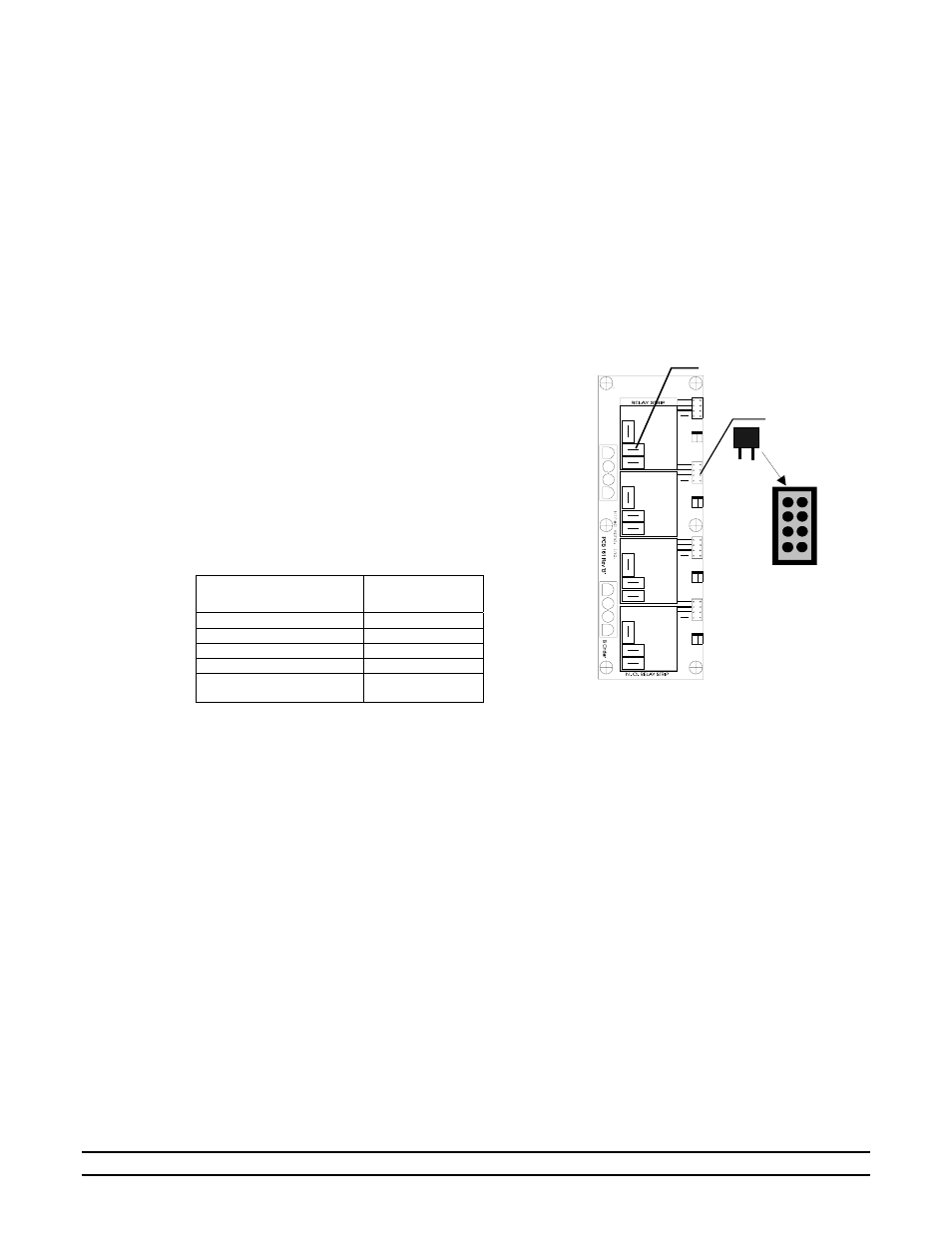
9.1.5 Setting EV Back-Up Stage Jumpers
Pictured at the right is a Stage Relay Board consisting
of four stage relays and the associated stage jumper for
each stage relay. This board is located in the EV-3000
or EV-3001 controller. The stage jumpers are labeled
COOL 1, COOL 2, COOL 3 and HEAT. Location of
the jumper places the equipment on one of these four
Back-Up Stages, or if the jumper is not inserted, the
equipment is not placed on Back-Up. The jumpers
should be placed based on the operation of stage
equipment and should be the same as assigned in the
EV-3000 Controller. Jumpers are placed according the
following table:
Type of Stage
Operation
Jumper
Assignment
Cool Negative Fan
COOL 1
Cool Negative Tunnel Fan
COOL 2
Cool Tunnel Fan
COOL 3
Heat Stage
HEAT
Stage not on Back-Up
No Jumper
Installed
Additional information can be found in the Evolution
3000 Owners Manual, Part Number 4801-5307.
9.1.6 Vent/Tunnel Inlet Override Operation
The S
3
Expansion contains override relays to operate your Vent or Tunnel inlets during Back-Up
situations. It is intelligent enough to understand how it needs to operate these overrides in a manner that
will not disrupt what the main control system is trying to do.
Typical operation results in the Tunnel inlet being overridden open anytime the Back-Up stage Cool3 is
on. Otherwise, if Cool1 or Cool2 is on, the S
3
Expansion will override the Vent inlets open. This is the
correct assumption most of the time but there are exceptions. It is important to note that if Cool3 is turned
on, the S
3
will turn off Cool1 which, in turn, will disable the Vent inlet override. This allows the Back-Up
system to perform in much that same manner as the main control system would function during tunnel
ventilation.
If connected to the Evolution 3000/3001, the S
3
Expansion communicates with the master controller.
Therefore, it is aware of what type ventilation mode the controller is currently in. For example, if the main
controller is in tunnel ventilation. The S
3
Expansion will not allow Cool1 to turn on. The reason is due to
the fact that it knows that this is your sidewall fans. Therefore, it understands that it would be detrimental
to the ventilation to turn them on. This, in turn, also disables the Vent inlets from opening.
STAGE RELAY BOARD
Stage Relay
COOL 3
COOL 2
COOL 1
HEAT
Stage
Jumpers