2 test/acknowledge alarm, 5 stage switch – Hired-Hand Emergency Back-Up and Alarms: Secondary Sensing System Expansion User Manual
Page 14
Manual No. 4801-3001 Rev 7-08
Secondary Sensing System Expansion
14 of 46
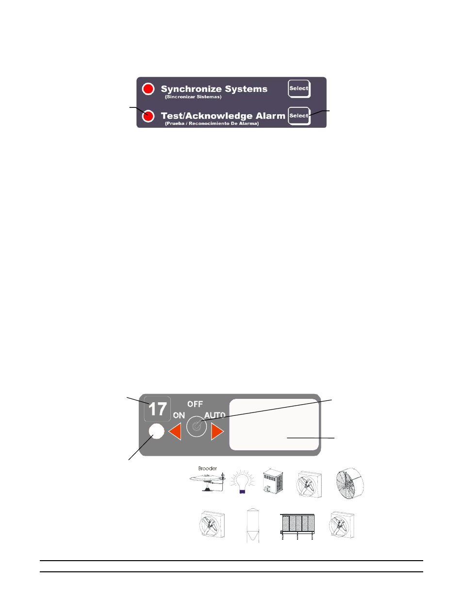
5.4.2 Test/Acknowledge
Alarm
The Test/Acknowledge Alarm Section has two functions. It allows the user the ability to test the
alarm contacts or the ability to silence (acknowledge) an active alarm.
Testing Alarm Contacts
To test the Alarm contacts, the user can simply press and hold the “Select” button next to the
Test/Acknowledge Alarm indicator. This allows the user the ability to manually test his
alarm siren and/or alarm dialer. As long as the button is depressed, it will activate the alarm
relay irregardless of the conditions that exist. In applications that use audible sirens, it is
recommended that the operator press the Test/Acknowledge Alarm button for at least five
seconds twice a week. In addition to insuring that the alarm is working correctly, the
sounding of the alarm helps to condition that livestock or poultry so they are not shocked by
the sound when an emergency condition arises.
Acknowledging Alarms
If an active alarm condition exists, you can silence the audible siren, phone dialer, etc. once
you arrive by pressing this button. This indicates to the alarm that you are acknowledging the
problem; therefore, it disables the alarm contacts. If a different alarm occurs after the
acknowledgement, the alarm contacts will be re-enabled. After an acknowledgement, the
alarm indicator will continue to blink and the indicator beside the Test/Acknowledge Alarm
section will also be on. This acknowledged condition is reset by only two ways. First, the
alarm condition is corrected; secondly, the AC power and the battery power are removed
from the controller.
5.5 Stage
Switch
The stage LED indicator lights when a stage is active. The stage switch is used to select AUTO operation,
ON, or OFF. If switch is in Auto position, the stage operation is controlled by the controller. That is, the
stage may turn on and off according to settings selected from the Main Display screen. If switch is in the
ON position, a stage is ON continuously. If switch is in the OFF position, a stage is OFF.
The white space is used to affix a label indicating stage function (i.e. brooder, fan, light, cool, etc.)
NOTE: Stages 1-16 are marked on Main panel. For optional stages 17-64, use stick-on label to number
stages.
1
1
Stage number
(Use labels to denote
stages 17-64)
ON, OFF, AUTO
Switch positions
Stick Icon label onto
white area or use for
notation
LED Indicator (lights
when stage is ON)
Icon labels are provided to
affix to white area of stage
control. Icon symbols are
shown at right.
Heater
Negative Fan
Light
Stir Fan
Neg./Tun.
Feed
Evap. Cooling
Tunnel Fan
Test/Acknowledge Alarm
Select Buttons
Test/
Acknowledge
Alarm
LED Display