Black box – Watlow 8LS Controller User Manual
Page 44
36 8LS User’s Guide
Installation
A termination resistor is required at each end of the transmission line.
This is accomplished by applying a 200
Ω
resistor across the line at the
farthest point from the computer transmitter. Check with Watlow
Anafaze for setting the Black Box SW2 to the "term" position to
terminate the computer receive line.
The fifth wire for RS-485 communications is recommended for noisy
environment.
NOTE
Connect the cable shields to equipment ground
only at the 8LS controller sites. Do not connect the
shield at the computer site to Ground. Connect a
200 ohm terminating resistor between RX- and
RX+ at the 8LS.
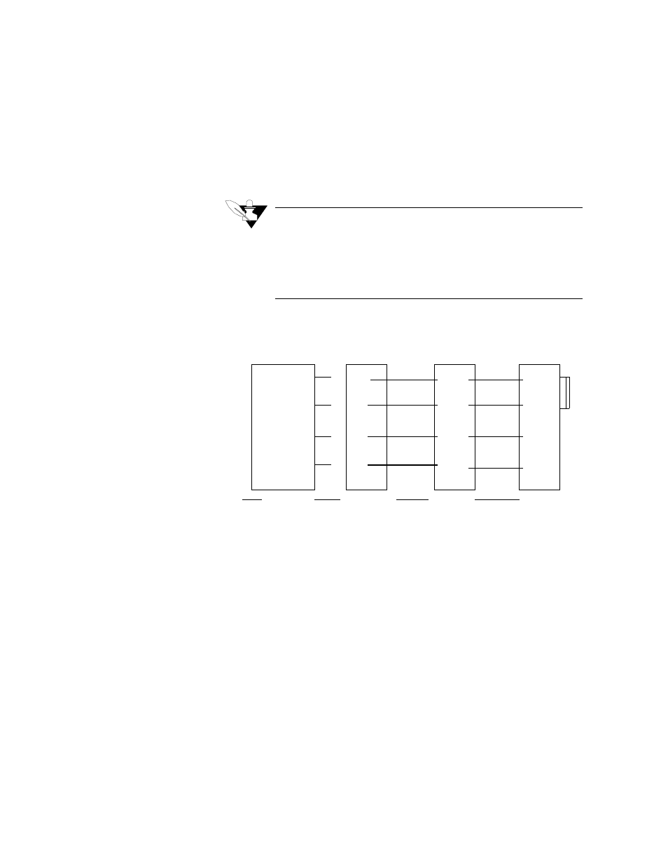
For multiple units connect the system in parallel as follows:
RX+ # 4
RX- # 5
TX+ # 2
TX- # 3
200
RX+ # 4
RX- # 5
TX+ # 2
TX- # 3
TXA
TXB
RXA
RXB
8LS (n)
8LS (1)
Black Box
LD485A
B&B Electronics
485OIS 485OIC
DB-25 Screws
Or
#2
#14
#5
#17
TDA
TDB
RDA
RDB
The "fifth"
12 VDC Com
12 VDC Com
Logic COM
Logic COM
wire
- 12LS Controller (111 pages)
- 8PID Controller (55 pages)
- Addendum to EZwarePlus (50 pages)
- ANASCAN (62 pages)
- ANASOFT (95 pages)
- ANAWIN 2 (154 pages)
- ANAWIN 3 (23 pages)
- Calibrating Watlow Series 988 Family Process Controls (19 pages)
- CAS (98 pages)
- CAS200 (124 pages)
- CLS (180 pages)
- CLS200 (251 pages)
- CLS200, MLS300 and CAS200 (92 pages)
- Control Console (12 pages)
- CPC400 (230 pages)
- DIN-A-MITE Style A (9 pages)
- DIN-A-MITE Style B (14 pages)
- DIN-A-MITE Style C (22 pages)
- DIN-A-MITE Style D (9 pages)
- DIN-Mount Adapter Instruction Sheet, Rev A (1 page)
- Dual DAC (4 pages)
- EM Gateway (28 pages)
- E-Safe Hybrid Relay Rev B (4 pages)
- E-SAFE II Hybrid Power Switch (4 pages)
- EZwarePlus Programming (264 pages)
- EZ-ZONE PM (111 pages)
- EZ-ZONE PM PID (125 pages)
- EZ-ZONE PM Express Limit (34 pages)
- EZ-ZONE PM Express (35 pages)
- EZ-ZONE PM Integrated Controller (181 pages)
- EZ-ZONE RM Limit Module Rev C (127 pages)
- EZ-ZONE RMA Modul (79 pages)
- EZ-ZONE RMC (236 pages)
- EZ-ZONE RME (124 pages)
- EZ-ZONE RMH (161 pages)
- EZ-ZONE RUI/Gateway (62 pages)
- EZ-ZONE RM-Scanner-Modul (140 pages)
- EZ-ZONE ST (97 pages)
- F4 External Event Board - Rev.B (2 pages)
- HG Series Mercury Displacement Relay (6 pages)
- LogicPro (296 pages)
- Mercury Relay or MDR Retrofit (13 pages)
- MICRODIN (24 pages)
- MICRODIN (106 pages)