Analog output dip switch setting for 0-5v/4-20ma – Watlow 8LS Controller User Manual
Page 38
30 8LS User’s Guide
Installation
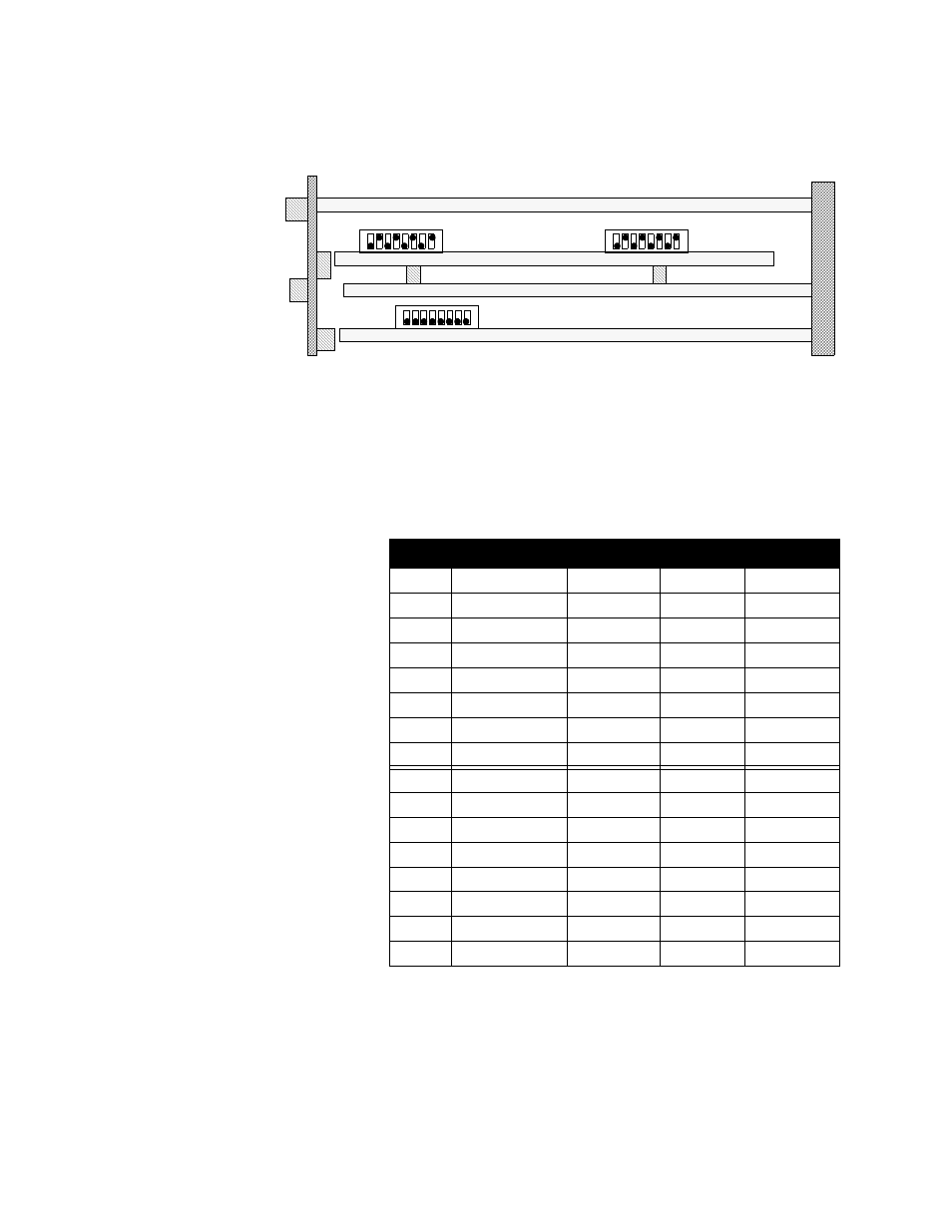
second is down, the output is in current mode. Thus if switch 3 is down
and 4 is up on the dip switch package near the rear panel, then channel 3
is set for voltage.
Output switches are set to voltage mode; in CPU switch all special
features are set to Off.
Analog Output Dip Switch Setting
for 0-5v/4-20mA
O indicates an On switch, F indicates an Off switch.
Loop
Switch
Position
0-5 Vdc
4-20 mA
1
Rear
1
O
F
1
Rear
2
F
O
3
Rear
3
O
F
3
Rear
4
F
O
5
Rear
5
O
F
5
Rear
6
F
O
7
Rear
7
O
F
7
Rear
8
F
O
2
Front
1
O
F
2
Front
2
F
O
4
Front
3
O
F
4
Front
4
F
O
6
Front
5
O
F
6
Front
6
F
O
8
Front
7
O
F
8
Front
8
F
O
1
8
1
8
1
8
Rear DIP Switch
Front DIP Switch
CPU DIP Switch
Odd
Even
O
F
O
F
o
F
See also other documents in the category Watlow Sensors:
- 12LS Controller (111 pages)
- 8PID Controller (55 pages)
- Addendum to EZwarePlus (50 pages)
- ANASCAN (62 pages)
- ANASOFT (95 pages)
- ANAWIN 2 (154 pages)
- ANAWIN 3 (23 pages)
- Calibrating Watlow Series 988 Family Process Controls (19 pages)
- CAS (98 pages)
- CAS200 (124 pages)
- CLS (180 pages)
- CLS200 (251 pages)
- CLS200, MLS300 and CAS200 (92 pages)
- Control Console (12 pages)
- CPC400 (230 pages)
- DIN-A-MITE Style A (9 pages)
- DIN-A-MITE Style B (14 pages)
- DIN-A-MITE Style C (22 pages)
- DIN-A-MITE Style D (9 pages)
- DIN-Mount Adapter Instruction Sheet, Rev A (1 page)
- Dual DAC (4 pages)
- EM Gateway (28 pages)
- E-Safe Hybrid Relay Rev B (4 pages)
- E-SAFE II Hybrid Power Switch (4 pages)
- EZwarePlus Programming (264 pages)
- EZ-ZONE PM (111 pages)
- EZ-ZONE PM PID (125 pages)
- EZ-ZONE PM Express Limit (34 pages)
- EZ-ZONE PM Express (35 pages)
- EZ-ZONE PM Integrated Controller (181 pages)
- EZ-ZONE RM Limit Module Rev C (127 pages)
- EZ-ZONE RMA Modul (79 pages)
- EZ-ZONE RMC (236 pages)
- EZ-ZONE RME (124 pages)
- EZ-ZONE RMH (161 pages)
- EZ-ZONE RUI/Gateway (62 pages)
- EZ-ZONE RM-Scanner-Modul (140 pages)
- EZ-ZONE ST (97 pages)
- F4 External Event Board - Rev.B (2 pages)
- HG Series Mercury Displacement Relay (6 pages)
- LogicPro (296 pages)
- Mercury Relay or MDR Retrofit (13 pages)
- MICRODIN (24 pages)
- MICRODIN (106 pages)