4 cabinet and rack installation, Figure 4-11: arm mounting retention screw holes – IEI Integration AFL2-12A-HM65 v1.00 User Manual
Page 52
AFL2-12A-HM65 Series Panel PC
Page 52
NOTE:
When purchasing the arm please ensure that it is VESA compliant and that
the arm has a 75 mm or 100 mm interface pad. If the mounting arm is not
VESA compliant it cannot be used to support the AFL2-12A-HM65 flat
bezel panel PC.
Step 2:
Once the mounting arm has been firmly attached to the surface, lift the flat bezel
panel PC onto the interface pad of the mounting arm.
Step 3:
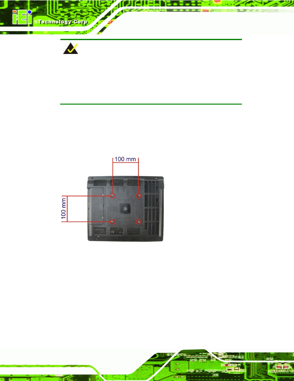
Align the retention screw holes on the mounting arm interface with those in the
flat bezel panel PC (Figure 4-11).
Figure 4-11: Arm Mounting Retention Screw Holes
Step 4:
Secure the flat bezel panel PC to the interface pad by inserting four retention
screws through the bottom of the mounting arm interface pad and into the flat
bezel panel PC.
Step 0:
4.8.4 Cabinet and Rack Installation
The AFL2-12A-HM65 flat bezel panel PC can be installed into a cabinet or rack. The
installation procedures are similar to the panel mounting installation. To do this, please
follow the steps below: