2 internal peripheral connectors, 1 12 v power connector (cn1), Nternal – IEI Integration TANK-6000-C226 User Manual
Page 40: Eripheral, Onnectors, Table 4-1: peripheral interface connectors, Table 4-2: 12 v power connector (cn1) pinouts
TANK-6000-C226 Em b e d d e d S ys te m
P a g e 30
4.2 In te rn a l P e rip h e ra l Co n n e c to rs
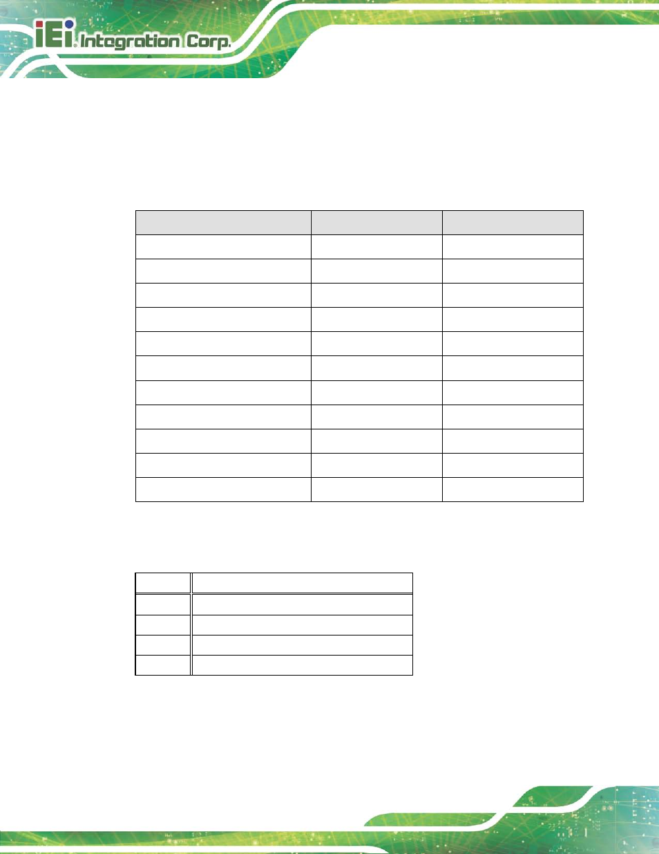
Internal peripheral connectors are found on the motherboard and are only accessible
when the motherboard is outside of the chassis. The table below shows a list of the
peripheral interface connectors on the TANK-6000-C226 motherboard. Pinouts of these
connectors can be found in the following sections.
Co n n e c to r
Typ e
La b e l
12 V power connector
4-pin Molex
CN1
Battery connector
2-pin wafer
BAT1
BMC debug connector
4-pin wafer
J2_BMC
EC debug port connector
20-pin FPC connector
CN2
Fan connectors
4-pin wafer
CPU_FAN1, SYS_FAN2
Flash BIOS ROM connector
6-pin wafer
JSPI1
Flash EC ROM connector
8-pin header
JSPI2
Flash BMC ROM connector
6-pin wafer
SPI1
OLED connector
6-pin wafer
OLED1
Power on connector
4-pin wafer
CN3
Serial ATA 3.0 connectors
Serial ATA 3.0 connector
SATA1
Table 4-1: Peripheral Interface Connectors
4.2.1 12 V P o we r Co n n e c to r (CN1)
PIN NO.
DESCRIPTION
1
GND
2
GND
3
VIN
4
VIN
Table 4-2: 12 V Power Connector (CN1) Pinouts