3 power-on procedure, 1 installation checklist, 2 terminal block pinouts – IEI Integration ECW-281B-N270-WT v3.01 User Manual
Page 71
ECW-281B/281B2-R30/N270 Embedded System
Page 56
4.3 Power-On Procedure
4.3.1 Installation Checklist
WARNING:
Make sure a power supply with the correct input voltage is being fed into
the system. Incorrect voltages applied to the system may cause damage to
the internal electronic components and may also cause injury to the user.
To power on the embedded system please make sure of the following:
The bottom surface panel is installed
All peripheral devices (VGA monitor, serial communications devices etc.) are
connected
The power cables are plugged in
The system is securely mounted
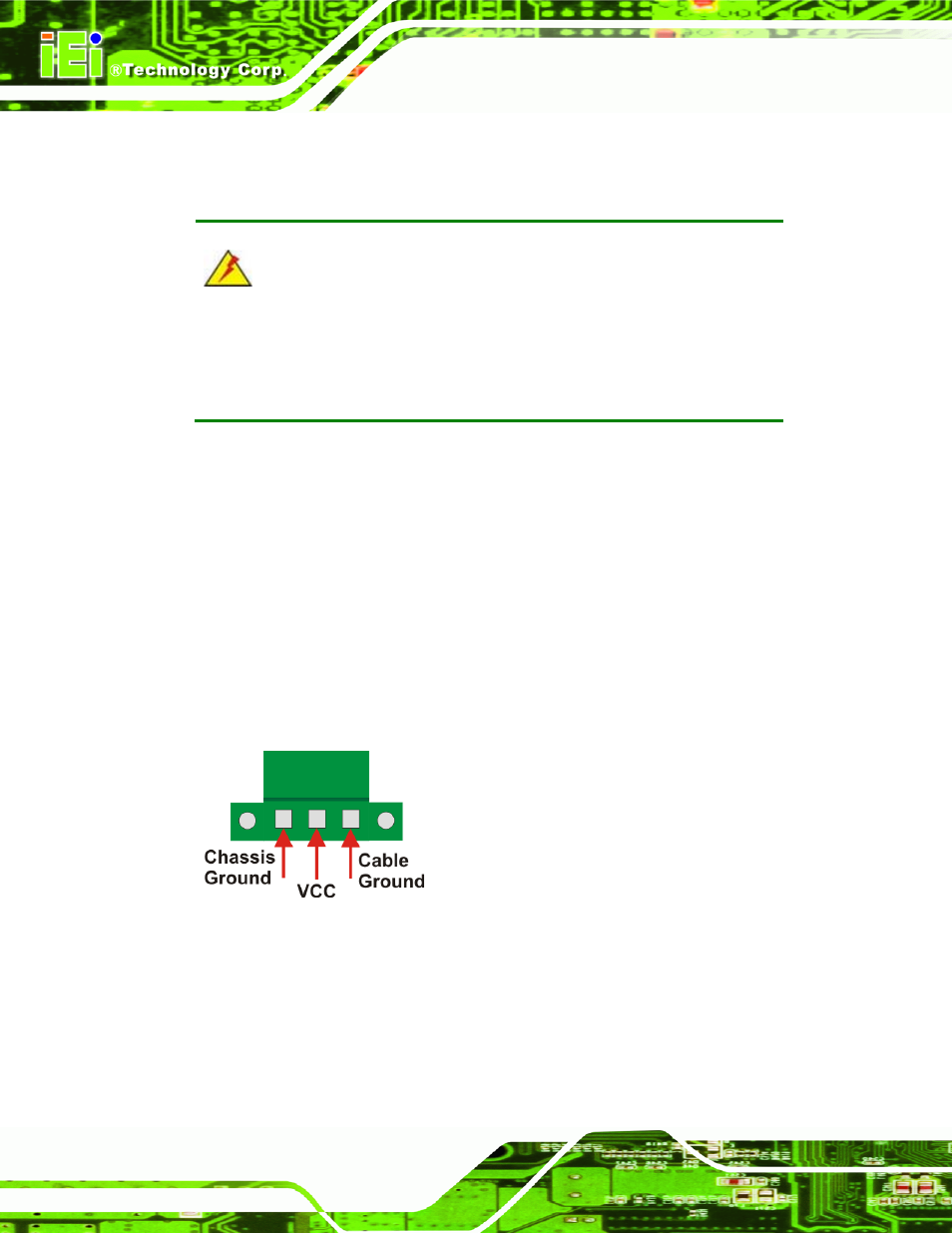
4.3.2 Terminal Block Pinouts
The terminal block pinouts are shown in
77
Figure 4-14
.
Figure 4-14: Terminal Block Pinouts
The chassis ground is connected to the ECW chassis internally. The cable ground is
connected to the ground pin on the input power connector of the power module.