6 vga monitor connection, Figure 4-18: usb connector – IEI Integration IMB-H612A User Manual
Page 78
IMB-H612 Mic ro -ATX Mo th e rb o a rd
P a g e 63
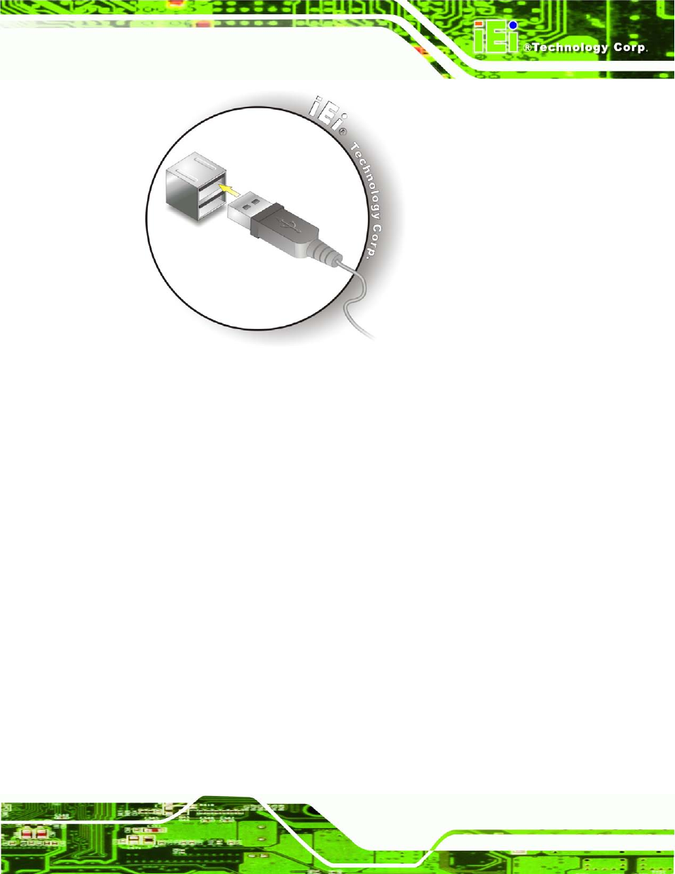
Figure 4-18: USB Connector
4.6.6 VGA Mo n ito r Co n n e c tio n
The IMB-H612 has two female DB-15 connectors on the external peripheral interface
panel. The DB-15 connector is connected to a CRT or VGA monitor. To connect a monitor
to the IMB-H612, please follow the instructions below.
S te p 1:
Locate the female DB-15 connector. The location of the female DB-15
connector is shown in Chapter 3.
S te p 2:
Align the VGA connector. Align the male DB-15 connector on the VGA screen
cable with the female DB-15 connector on the external peripheral interface.
S te p 3:
Insert the VGA connector
.
Once the connectors are properly aligned with the
insert the male connector from the VGA screen into the female connector on the
IMB-H612. See Figure 4-19.