D.1 introduction, D.2 dio connector pinouts, D.3 assembly language samples – IEI Integration IMB-H612A User Manual
Page 189: D.3.1 enable the dio input function, Ntroduction, Onnector, Inouts, Ssembly, Anguage, Amples
IMB-H612 Mic ro -ATX Mo th e rb o a rd
P a g e 174
D.1 In tro d u c tio n
The DIO connector on the IMB-H612 is interfaced to GPIO ports on the Super I/O chipset.
The DIO has both 4-bit digital inputs and 4-bit digital outputs. The digital inputs and digital
outputs are generally control signals that control the on/off circuit of external devices or
TTL devices. Data can be read or written to the selected address to enable the DIO
functions.
NOTE:
For further information, please refer to the datasheet for the Super I/O
chipset.
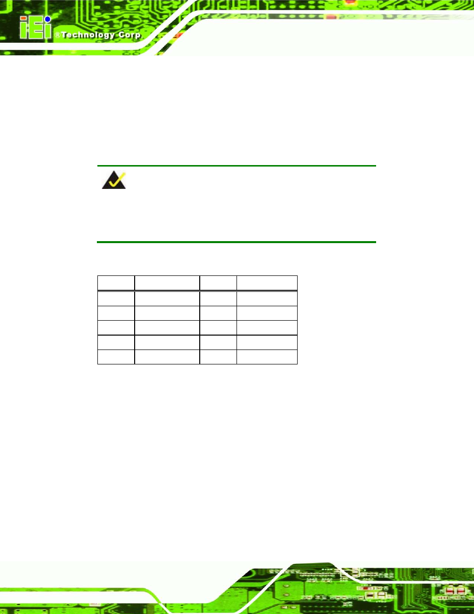
D.2 DIO Co n n e c to r P in o u ts
PIN NO. DESCRIPTION
PIN NO. DESCRIPTION
1
GND
2
+5V
3
DGPO3
4
DGPO2
5
DGPO1
6
DGPO0
7
DGPI3
8
DGPI2
9
DGPI1
10
DGPI0
Table 6-1: Digital I/O Connector Pinouts
D.3 As s e m b ly La n g u a g e S a m p le s
D.3.1 En a b le th e DIO In p u t Fu n c tio n
The BIOS interrupt call INT 15H controls the digital I/O. An assembly program to enable
digital I/O input functions is listed below.
MOV
AX, 6F08H
Sets the digital port as input
INT
15H
Initiates the INT 15H BIOS call