2 ethernet and usb connectors, Figure 3-23: lan connector, Table 3-22: lan connector pinouts – IEI Integration IMB-H612A User Manual
Page 55
IMB-H612 Mic ro -ATX Mo th e rb o a rd
P a g e 40
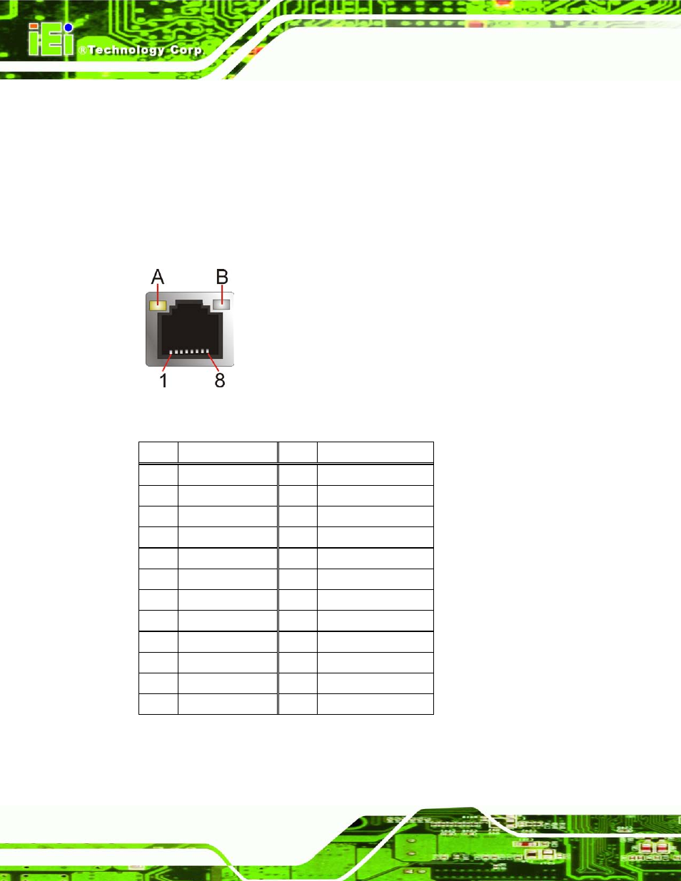
3.3.2 Eth e rn e t a n d US B Co n n e c to rs
CN La b e l:
LAN1_US B01, LAN2_US B23
CN Typ e :
RJ-45, USB
CN Lo c a tio n :
CN P in o u ts :
See Table 3-22, Table 3-23 and Table 3-24
The LAN connector connects to a local network.
Figure 3-23: LAN Connector
PIN
DESCRIPTION
PIN
DESCRIPTION
P1
TC
P2
LAN1/2_MDI0+
P3
LAN1/2_MDI0-
P4
LAN1/2_MDI1+
P5
LAN1/2_MDI1-
P6
LAN1/2_MDI2+
P7
LAN1/2_MDI2-
P8
LAN1/2_MDI3+
P9
LAN1/2_MDI3-
P10
GND
P11
LAN1/2_LINK1000
P12
LAN1/2_LINK1000
P13
LAN1/2_ACT-1 LED
P14
VCC
P15
GND
P16
GND
9
GND
10
GND
11
GND
12
GND
13
GND
14
GND
15
GND
16
GND
Table 3-22: LAN Connector Pinouts
The USB connector can be connected to a USB device.
This manual is related to the following products: