Figure 3-20: usb connector pinout locations, Table 3-18: usb port connector pinouts (usb45), Table 3-19: usb port connector pinouts (usb67) – IEI Integration IMB-H612A User Manual
Page 52
IMB-H612 Mic ro -ATX Mo th e rb o a rd
P a g e 37
CN P in o u ts :
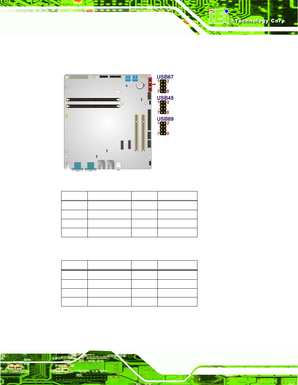
See Table 3-18, Table 3-19 and Table 3-20
The USB connectors connect to USB devices. Each pin header provides two USB ports.
Figure 3-20: USB Connector Pinout Locations
PIN NO.
DESCRIPTION
PIN NO.
DESCRIPTION
1
VCC
2
GND
3
DATA4_N
4
DATA5_P
5
DATA4_P
6
DATA5_N
7
GND
8
VCC
Table 3-18: USB Port Connector Pinouts (USB45)
PIN NO.
DESCRIPTION
PIN NO.
DESCRIPTION
1
VCC
2
GND
3
DATA0_N
4
DATA1_P
5
DATA0_P
6
DATA1_N
7
GND
8
VCC
Table 3-19: USB Port Connector Pinouts (USB67)
This manual is related to the following products: