Warner Electric PCBC-1525_1225 User Manual
Page 8
8
Warner Electric • 800-825-9050
P-214
•
819-0518
PCB-1225/1000, PCB-1525/1225
Clutch-Brake Spline Drive Armature
The illustration drawings, parts lists, and exploded
views for these units can be found beginning on
page 20.
Refer to the installation instructions for pin drive
armature units, page 3, for steps A-E.
F. Assembling the Spline Drive Clutch
Armature
1. These clutch/brake units contain spline drive
armatures and hubs. The armatures are shipped
with a built-in autogap spring accessory. This
device automatically maintains a gap of about
1/32 inch between the armature and magnet
faces for the life of the unit.
The spline drive armature assembly is shipped
with the armature, splined armature adapter,
and autogap already assembled. The splined
hub and capscrew accessories are shipped as
separate parts.
Follow these instructions to assemble the
splined armature assembly and hub:
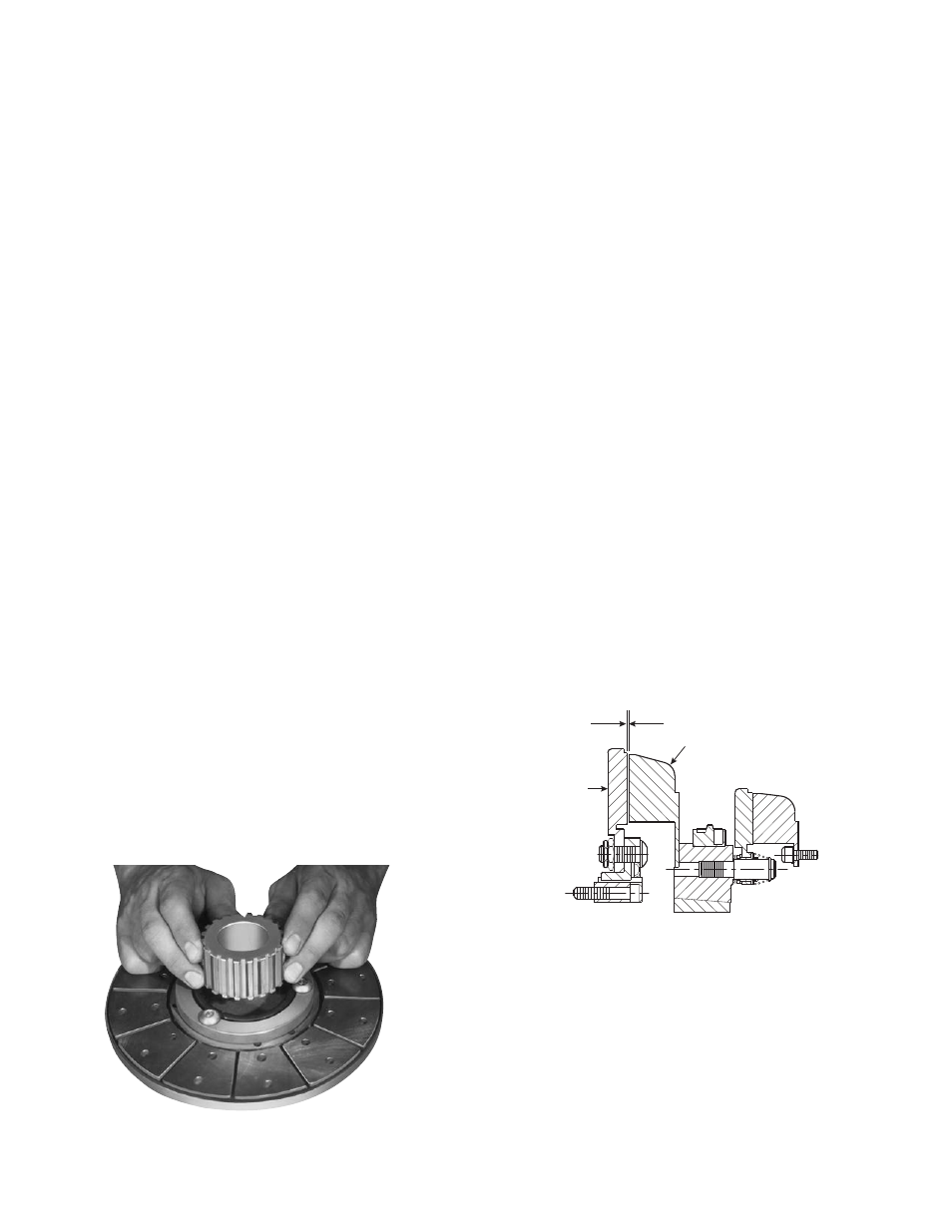
a. Place the armature-adapter assembly on a
flat surface with the segmented side up.
b. Push the splined hub, with the pilot diameter
down (refer to illustration drawings) through
the autogap spring and splined armature
adapter. (Figure 12)
2. A customer may mount the clutch armature to
his own pulley, hub, gear, etc. Refer to the illus-
tration drawings, "End View of the Armature,"
page 20, for the dimensional information need-
ed to drill and tap holes in the customer part.
The splined hub pilot diameter must be concen-
tric with the splined armature center of rotation
within .010 T.I.R.
3. Mount the armature to the customer's part
using the capscrew accessory provided.
Maintain a 1/16-inch clearance between the
armature adapter and the customer part after
the parts have been assembled.
G. Mounting the Clutch Armature
Assembly
1. Slide the complete armature assembly on to the
shaft.
2. Adjust the armature's position to allow a 1/16-
inch gap between the magnet and armature
faces. (Figure 13)
3. Secure the armature and customer supplies
pulley, sprocket or hub assembly in position by
a) retainer rings, b) set collars, c) shoulder on
the shaft, or d) any combination of these. The
best method will depend on the characteristics
of each application.
Figure 12
1/32-inch
Clutch Magnet
Armature
Figure 13