Warner Electric PCBC-1525_1225 User Manual
Page 5
5
Warner Electric • 800-825-9050
P-214
•
819-0518
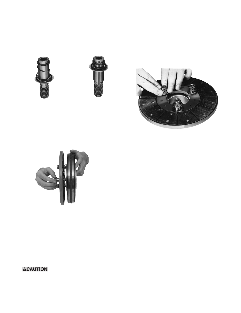
Step 2
Compress the heavy (red) spring on each drive pin
by sliding detent spring towards the head of the
pin. (Figure 8)
Step 3
Insert assembled drive pins through armature
(entering from segmented side), through straight
(white) springs, and into magnet hub. (Figure 9)
Note: Apply Grade "AA" Loctite
®
Sealant on pin
threads.
Step 4
Tighten the pins until the shoulders of the pins are
against the face of the hub. Since threads are class
No. 3 fit, pins may seem to bind.
The straight springs must not
get caught under shoulders of drive pins.
Step 5
Check to see that the armature is completely com-
pressed against the face of the hub.
Step 6
To set the autogap, slide the detent spring retain-
ers against the armature face. (Figure 10)
Note: This position must not be disturbed during
completion of assembly.
E. Mounting the Magnet-Hub-Armature
Assembly
This assembly is mounted on the shaft with a
taperlock bushing. All parts must be clean and free
from burrs and chips before assembling.
1. Place the bushing into the hub, and insert the
key. The key is a side-to-side fit and should not
contact the top of the keyway.
2. Insert the locking setscrews loosely into the
bushing, and slide the assembly onto the shaft.
Figure 8
Figure 9
Figure 10