C. assembling the clutch magnet and magnet hub, D. assembling the brake armature and magnet hub, Figure 4 figure 5 figure 6 – Warner Electric PCBC-1525_1225 User Manual
Page 10
10
Warner Electric • 800-825-9050
P-214
•
819-0518
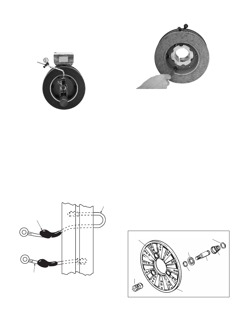
4. Use a dial indicator to check the unit for con-
centricity and squareness to the shaft. The unit
should be concentric within .010 T.I.R. and
square within .006 T.I.R. (See Figure 3.)
C. Assembling the Clutch Magnet and
Magnet Hub
1. Insert the lead wires through the rubber termi-
nal caps and onto the collector ring. The short-
er wire goes into the hole in the front of the ring
(the side that will be mounted to the magnet).
The longer wire goes through the ring and into
the hole in the back.
Press the bullet-type connectors firmly into
place. (See Figure 4.)
2. Mount the magnet to the magnet hub using
capscrews and lockwashers. (See Figure 5.)
3. Secure the lead wires to the magnet terminals
with screws and lockwashers.
4. Pull the rubber caps over the terminals.
D. Assembling the Brake Armature and
Magnet Hub
Assemble the armature to the magnet hub with the
autogap mounting accessory.
The autogap assembly is a double spring device
which allows for automatic armature clearance and
adjustment for wear. The smaller or conical spring
pushes the armature from the magnet face, leaving
a gap of about 1/32 inch, while the straight spring
automatically follows up for wear. This combination
maintains maximum efficiency throughout the life of
the unit.
The assembly procedure for the autogap accesso-
ry is as follows (Figure 6):
Figure 3
Short
Wire
Collector
Ring
Terminal
Cap
Long
Wire
Figure 4
Figure 5
Figure 6
Retainer Ring
Heavy
Spring
(Red)
Detent
Spring
Retainer
Detent
Spring
Drive
Pin
Straight
Spring
(White)
Armature
Boss
Armature