Warner Electric PCBC-1525_1225 User Manual
Page 13
13
Warner Electric • 800-825-9050
P-214
•
819-0518
Step 3
Slide the armature-adapter assembly up against
the retainer ring.
Step 4
Insert the bushing into the retainer ring side of the
splined hub. The clearance holes in the bushing
flange should line up with the tapped holes in the
splined hub. (Figure 14)
G. Mounting the Armature and Hub
Assembly
1. Slide the complete armature and hub assembly
onto the shaft until the armature face touches
the magnet face.
2. Tighten the bushing capscrews, taking a few
turns at a time on each capscrew. As the cap-
screws are tightened, the armature will back
away slightly from the magnet. There should be
a clearance of 1/16" between the armature and
magnet when the capscrews are completely
tight.
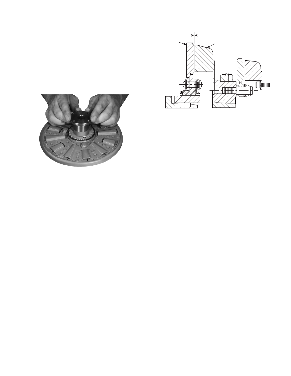
3. When the bushing is secure on the shaft, push
the armature against the magnet face. When
the armature is released, it will spring back
about 1/32". The gap will be automatically
maintained for the life of the unit.
(Figure 15)
H. Mounting the Brushholder
1. The brushholder is mounted on a bracket which
must be furnished by the customer. The bracket
must be firmly secured to prevent vibration
which could cause improper contact between
the brushes and collector ring.
2. The distance from the centerline of the shaft to
the top of the brushholder should be 5-3/4".
Maintaining this distance will assure proper
spring tension on the brushes and maximum
wear follow-up. A detailed dimensional drawing
is included with each brushholder.
Figure 14
1/32-inch
Clutch Magnet
Armature
Figure 15