Warner Electric PCBC-1525_1225 User Manual
Page 19
19
Warner Electric • 800-825-9050
P-214
•
819-0518
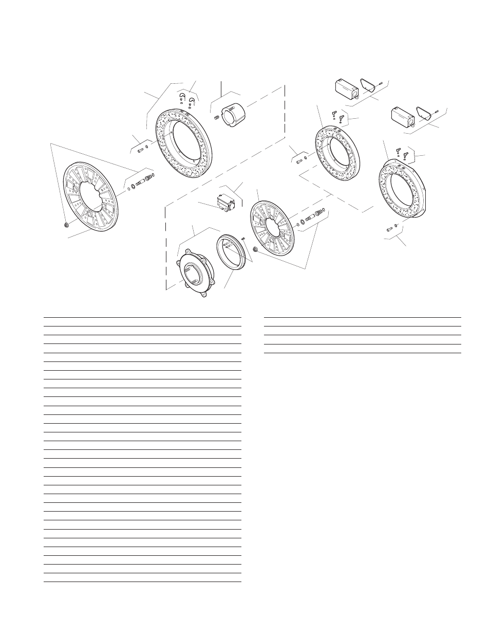
How to Order:
1. Specify Voltage for Item 4 and Item 11A or 11B.
2. Specify left hand or right hand hub for Item 5.
Bushing enters from magnet side for L.H. hub
and from hub side for R.H.
3. Specify Bore Size for Item 7.
4. Specify Inside Mounted for Items 10A and 11A
or Outside Mounted for Items 10B and 11B.
Example:
PCB-1525/1225 Clutch Brake per I-25635 - 90
Volt, Left Hand hub, 2" Bore, Inside Mounted
These units meet the standards of UL508 and are
listed under guide card #NMTR2, file #59164.
These units are CSA certified under file #LR11543.
1
2
3
6-1
6
8
5-1
5-2
9
10B
11B-1
12
12
11A-1
11A
10A
11B
4
4-1
7
5
(Shipped Assembled)
Item
Description
Part Number
Qty.
1
Armature
5304-111-004
1
2
Autogap Accessory
5201-101-008
4
3
Mounting Accessory
5321-101-001
1
4
Magnet
1
6 Volt
5304-631-009
24 Volt
5304-631-011
90 Volt
5304-631-010
4-1
Terminal Accessory
5311-101-001
1
5
Magnet Hub
1
Left Hand (shown)
5304-541-001
Right Hand
5304-541-002
5-1
Collector Ring
5301-749-001
1
5-2
Collector Ring Accessory
5304-101-004
1
6
Brushholder
5300-178-001
1
6-1
Brush
176-0001
4
7
Bushing*
1
15/16" to 3" Bore
180-0262 to 180-0295
8
Armature
5303-111-009
1
9
Autogap Accessory
5201-101-008
4
10A
Mounting Assembly - I.M.
5321-101-001
1
10B
Mounting Accessory - O.M.
5321-101-002
2
11A
Magnet - Inside Mounted
1
6 Volt
5313-631-005
24 Volt
5313-631-006
90 Volt
5313-631-007
11A-1 Terminal Accessory
5311-101-001
1
11B
Magnet - Outside Mounted
1
6 Volt
5313-631-010
24 Volt
5313-631-012
90 Volt
5313-631-011
Item
Description
Part Number
Qty.
11B-1 Terminal Accessory
5311-101-001
1
12
Conduit Box
5200-101-010
1
*See page 28 for specific part numbers.
PCB-1525/1225 Clutch/Brake – Normal Duty
Drawing I-25635