F. assembling the clutch armature – Warner Electric PCBC-1525_1225 User Manual
Page 6
6
Warner Electric • 800-825-9050
P-214
•
819-0518
3. Position the assembly to allow a gap of about
1/32-inch between the brake magnet and arma-
ture faces. (Figure 11)
Once this gap is set, it will be automatically
maintained for the life of the unit.
4. Secure the assembly in this position on the
shaft by alternately tightening each setscrew.
During the tightening process, the bushing
should be tapped lightly to make certain it
seats-in properly.
Note: For pin drive armatures (normal duty), con-
tinue to F. on page 7. For spline drive armatures
(heavy duty), proceed to F. on page 7.
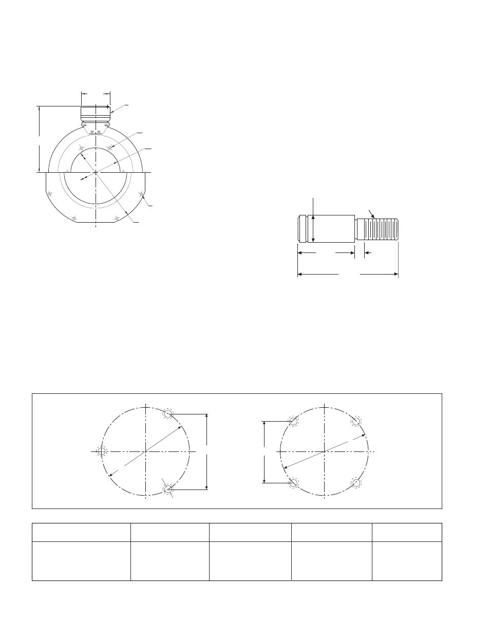
F. Assembling the Clutch Armature
1. A customer may wish to use the autogap
accessory to mount a clutch armature to his
own pulley, hub, gear, etc. Follow the illustrated
dimensions (Figures 12 & 13) to properly adapt
these parts to the armature.
a. Chordal dimensions "A" and "C" must be
held for all chords between pin holes.
b. Drill 27/64-inch diameter holes to a sufficient
Figure 11
Figure 12
Machining Instructions for Gear, Sprocket, or Pulley
Unit Size
A
B
C
D
1000
4.548 ± .002
5.252 ± .002
1225
4.155 ± .002
5.877 ± .002
1525
6.010 ± .002
8.500 ± .002
A
C
D
B
1-9/32"
5/16"
2-1/4"
1/2"–13 UNC–3A
Threads
+.0005"
.6185"
Dia.
–.0010"
Figure 13
Removable plug in
ends for 1/2" con
-
duit.
7.687 Max.
11.500/11.498 Pilot
Dia.
.358/.338 dia. (8) holes equally
spaced on 10.625 dia.*
.358/.338 dia. (6) holes
equally spaced on 6.125 dia.*
5.378/5.376 Pilot
Dia.
3.750