Warner Electric PCBC-1525_1225 User Manual
Page 12
12
Warner Electric • 800-825-9050
P-214
•
819-0518
E. Mounting the Magnet-Hub-Armature
Assembly
This assembly is mounted on the shaft with a
taperlock bushing. All parts must be clean and free
from burrs and chips before assembling.
1. Place the bushing into the hub, and insert the
key. The key is a side-to-side fit and should not
contact the top of the keyway.
2. Insert the locking setscrews loosely into the
bushing, and slide the assembly onto the shaft.
3. Position the assembly to allow a gap of about
1/32-inch between the brake magnet and arma-
ture faces. (Figure 11)
Once this gap is set, it will be automatically
maintained for the life of the unit.
4. Secure the assembly in this position on the
shaft by alternately tightening each setscrew.
During the tightening process the bushing
should be tapped lightly to make certain it
seats-in properly.
F. Assembling the Clutch Armature
The spline drive armatures are shipped with a built-
in autogap spring accessory. This device automati-
cally maintains a gap of about 1/32-inch between
the armature and magnet faces for the life of the
unit.
These units are shipped with the armature, splined
armature adapter, and autogap already assembled.
The splined hub, retainer ring, and bushing are
shipped as separate parts.
Follow these instructions to assemble the armature
and splined hub.
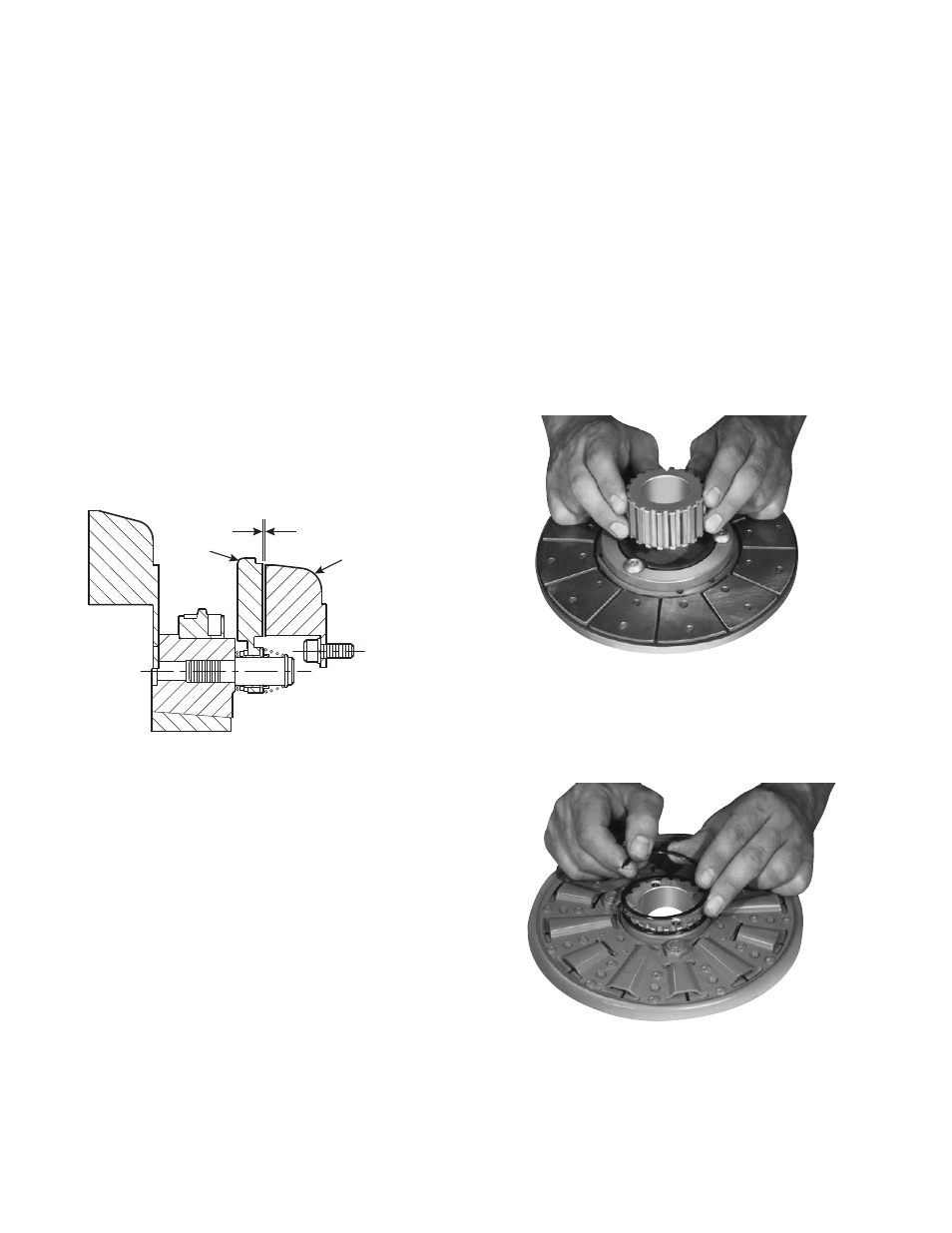
Step 1
Place the armature-splined adapter assembly on a
flat surface with the segmented side up. Push the
splined hub, with the retainer ring groove down,
through the autogap spring and splined armature
adapter. (Figure 12)
Step 2
Turn the armature-adapter assembly over, and
insert the retainer ring in the groove. (Figure 13)
1/32-inch
Brake Magnet
Armature
Figure 11
Figure 12
Figure 13