Warner Electric PCBC-1525_1225 User Manual
Page 3
3
Warner Electric • 800-825-9050
P-214
•
819-0518
Clutch-Brake
Pin Drive Armatures
PCB-1225/1000, PCB-1525/1225
The illustration drawings, parts lists, and exploded
views for these units can be found beginning on
page 16.
The brake half of the clutch/brake unit is usually
installed first; however, in some cases it may be
necessary to start with the clutch portion of the
unit to assure a proper assembly when complete.
A. Installing the Conduit Box
Install the conduit box on the brake magnet.
Instructions for this procedure can be found with
conduit box.
B. Mounting the Brake Magnet
The brake magnet is mounted to a stationary
machine member by a flange. Extreme care must
be taken in selecting the location for the mounting
of the magnet. Proper positioning is very important
for the unit to function correctly.
1. A pilot diameter on the mounting surface is
essential to hold the magnet within the required
tolerances. (See Figure 1.)
2. A machined pilot diameter is provided on the
magnet mounting flange (refer to illustration
drawings, page 16) to aid in the proper position-
ing of the magnet.
3. Once the mounting surface has been prepared,
the magnet is bolted in place with capscrews
and lock-washers. (See Figure 2.)
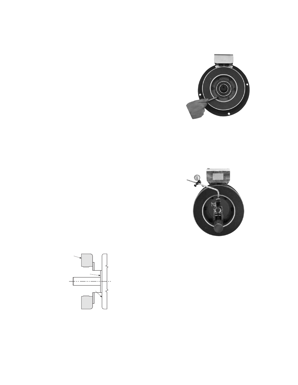
4. Use a dial indicator to check the unit for con-
centricity and squareness to the shaft. The unit
should be concentric within .010 T.I.R. and
square within .006 T.I.R. (See Figure 3.)
C. Assembling the Clutch Magnet and
Magnet Hub
1. Insert the lead wires through the rubber terminal
caps and into the collector ring. The shorter
wire goes into the hole in the front of the ring
(the side that will be mounted to the magnet).
The longer wire goes through the ring and into
the hole in the back.
Magnet
Pilot diameter
Mounting Surface
Figure 1
Figure 2
Figure 3