Warner Electric PCBC-1525_1225 User Manual
Page 7
7
Warner Electric • 800-825-9050
P-214
•
819-0518
depth and tap for 1/2-13 NC-3 1-1/8-inch
minimum full threads. Pin holes must be
square with plane of mounting surface and
magnet mounting.
c. Ream .501/.500 to a 3/8-inch depth and to
be concentric with tapped holes.
2. Once the pulley, gear, etc., has been adapted
to the armature according to the above direc-
tions, it may be mounted to the armature using
the autogap accessory.
The procedure is the same as described for the
brake armature (Step D, page 4), except that
the clutch armature is mounted with four drive
pins instead of three as shown in the illustra-
tion.
G. Mounting the Clutch Armature
1. Slide the armature and customer supplied pul-
ley, sprocket, or hub assembly onto the shaft.
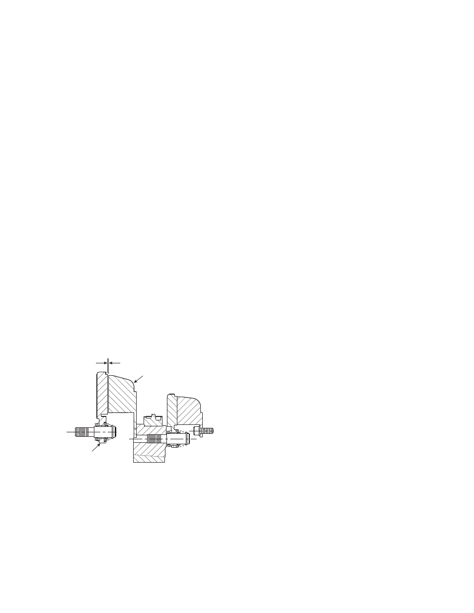
2. Adjust the armature's position to allow a 1/32"
gap between the magnet and armature faces.
(See Figure 14.)
Once this gap is set, it will be automatically
maintained for the life of the unit.
3. The armature and customer supplied pulley,
sprocket, or hub can be held in position on the
shaft by (a) retainer rings, (b) set collars, (c) a
shoulder on the shaft, or (d) any combination of
these. The best method will depend on the
characteristics of each application.
H. Mounting the Brushholder
1. The brushholder is mounted on a bracket which
must be furnished by the customer. The bracket
must be firmly secured to prevent vibration
which could cause improper contact between
the brushes and collector ring.
2. The distance from the centerline of the shaft to
the top of the brushholder should be 5-3/4".
Maintaining this distance will assure proper
spring tension on the brushes and maximum
wear follow-up. A detailed dimensional drawing
is included with each brushholder.
1/32-inch
Clutch Magnet
Armature
Figure 14