Control unit – TREND NX Variable Speed Drives User Manual
Page 77
60 • vacon
CABLING AND CONNECTIONS
Tel. +358 (0)201 2121 • Fax +358 (0)201 212 205
6
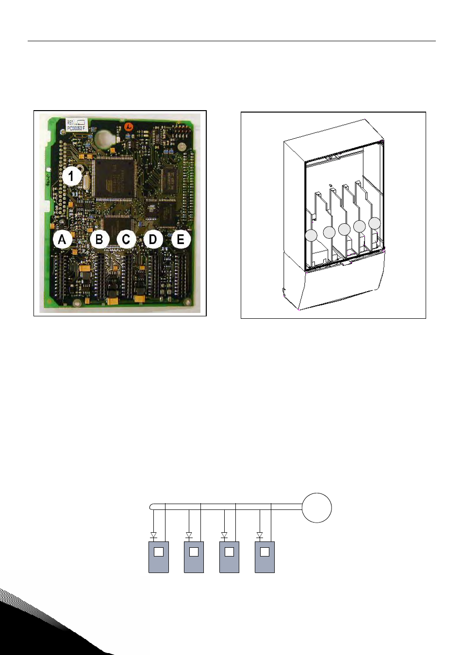
6.2 Control
unit
The control unit of the frequency converter consists roughly of the control board and additional boards (see
Figure 6-21 and Figure 6-22) connected to the five
slot connectors
(A to E) of the control board. The control
board is connected to the power unit through a D-connector (1) or fibre optic cables (FR9).
Figure 6-21. NX control board
Figure 6-22. Basic and option board connections
on the control board
Usually, when the frequency converter is delivered from the factory, the control unit includes at least the
standard compilation of two basic boards (I/O board and relay board) which are normally installed in slots
A and B. On the next pages you will find the arrangement of the
control I/O and the relay terminals
and the
. The I/O boards mounted
at the factory are indicated in the type code. For more information on the option boards, see Vacon NX
option board manual (ud741).
The control board can be powered externally (+24V, ±10%) by connecting the external power source to
either of the bidirectional terminala #6 or #12, see page 63. This voltage is sufficient for parameter setting
and for keeping the fieldbus active.
Note! If the 24V inputs of several frequency converters are parallelly connected we recommend to use a
diode in terminal #6 (or #12) in order to avoid the current to flow in opposite direction. This might damage
the control board. See picture below.
A
B
C
D
E
+
-
#6
#7
+
-
#6
#7
+
-
#6
#7
+
-
#6
#7
nk6_17
External
+24V