5 nx drive with duty/standby motors, Nx drive with duty/standby motors – TREND NX Variable Speed Drives User Manual
Page 18
Installation on a Trend System
2.2.5
NX drive with duty/standby motors
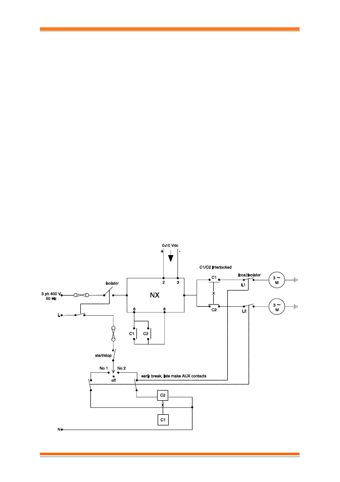
This system drives 2 motors in duty/standby e.g. they are both mounted on a
common drive shaft.
The motors are controlled by a three position switch (Motor 1, Off, Motor 2).
If Motor 1 is selected, then closing the start contact will energise the C1 coil
which will connect terminals 6 and 8 together, and connect the output of the
drive to motor 1.
Since the C1 and C2 motor contacts are mechanically interlocked so that
closing one prevents the other from closing; closing C1 will stop C2 closing
and switch off motor 2.
In the Off position neither motor can operate.
Since the circuit is symmetrical, in the Motor 2 position, motor 2 is switched
on and motor 1 is switched off.
The local isolators (L1, L2) will isolate the appropriate motor.
Note that since the C1 and C2 contacts are in parallel across terminals 6 and
8, the motors can operate independently unlike example 1.2.4 above where
they can only operate together.
16
NX Variable Speed Drives Installation Manual TG200434 Issue 3/A 04/07/2006