Installation, 1 system components/packing list, 2 analyzer led descriptions – Teledyne LeCroy BTTracer_Trainer - BTTracer Users Manual User Manual
Page 19: Upas leds (from left to right), Chapter 2 installation
9
BTTracer Protocol Analyzer User’s Manual
CATC
SW Version 2.20
2. Installation
The BTTracer Protocol Analyzer components and software are easily
installed and quickly ready to run on most Windows-based personal
computer systems. You can begin making Bluetooth recordings after
following these initial steps.
2.1 System Components/Packing List
•
One stand-alone BTTracer Analyzer module
•
One Antenna
•
One External Interface Breakout Board with a 25-pin ribbon cable
•
One USB cable
•
One SMA Adapter cable (for changing the polarity from reversed to
standard. This cable is used for creating wired piconets.)
•
HCI Probe
•
BTTracer software program installation CD
•
User Manual
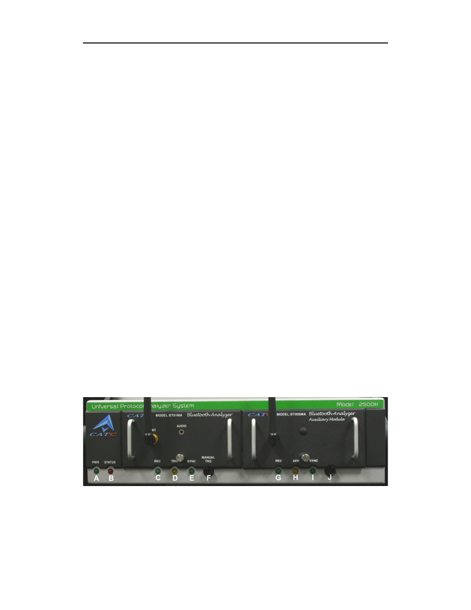
2.2 Analyzer LED Descriptions
With single probe system, the BTTracer analyzer module occupies the left
slot on the CATC Universal Protocol Analyzer System (UPAS). When
powered on, the BTTracer activates the user-accessible controls and LEDs
on the front and rear panels of the UPAS.
Warning Do not open the UPAS enclosure. There are no operator serviceable
parts inside. Refer servicing to CATC.
UPAS LEDs (from left to right)
A Green PWR (power) indicator LED for UPAS (lights when the unit
power is switched on).