Back and side inputs/outputs – Teledyne LeCroy WaveAce 1000_2000 User Manual
Page 14
WaveAce 1000/2000
8
922131-00 Rev A
Back and Side Inputs/Outputs
The following image shows back panel connection locations for the 4 Channel
models.
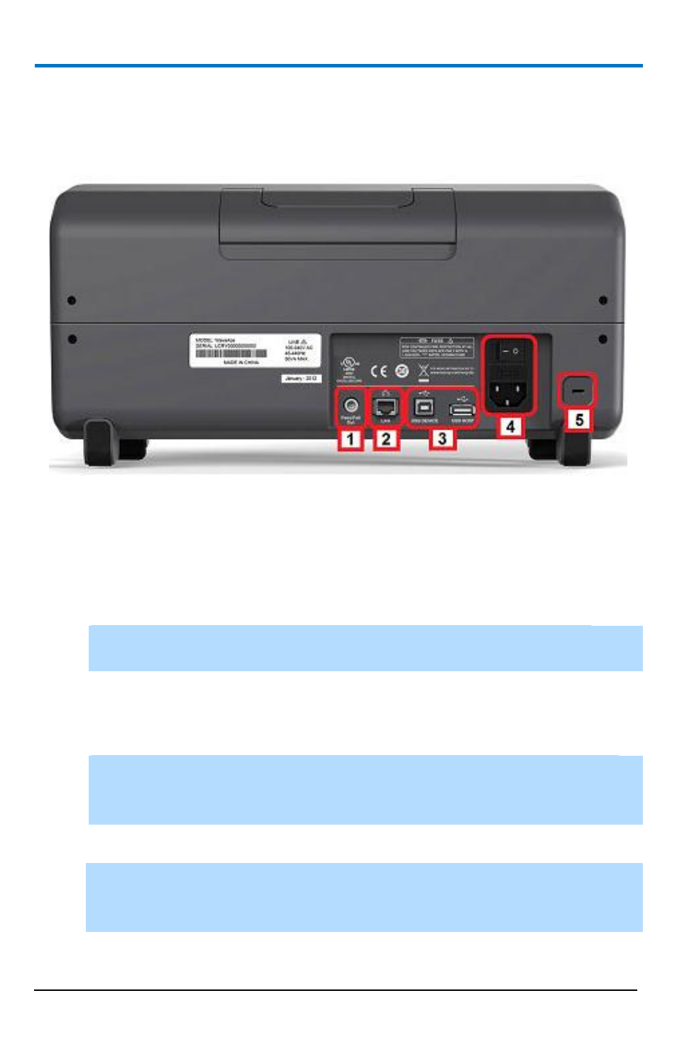
Back panel connection locations on the 4 Channel WaveAce Oscilloscope.
Previously numbered front panel buttons and knob locations on 4 Channel
models correspond with the following explanations.
1. Pass/Fail Output
2. RJ-45 Connector
NOTE: For more information, see Using WaveStudio to Remotely
Connect to your WaveAce Oscilloscope (on page 90).
3. Rear USB (Type B and Type A, respectively) Connectors. Use the Type B
connector to attach a printer to your instrument. The Type A connector
is designated for memory stick use just like the one on the Front Panel.
NOTE: If you simultaneously connect separate memory sticks to both
the front and back Type A connectors, the WaveAce defaults to only
using the one attached to the front connector.
4. Power Shutoff Switch and Input Connector
NOTE: The WaveAce 1000 model has
a
Power Input Connector
and no
Power Shutoff Switch on the left side (facing) of the instrument instead
of the back.
5. Security Lock Receptacle