4 wiring diagram, 77 7. specifi cations – IAI America IX-NNC8040 User Manual
Page 83
77
7. Specifi
cations
7.4 Wiring
Diagram
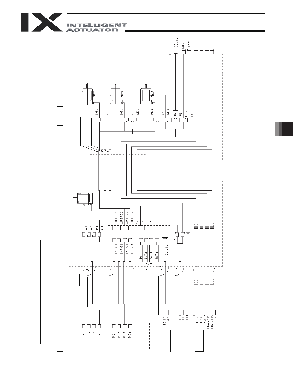
Wiring/Piping Diagram (Arm Length: 500/600)
Co
n
tro
lle
r
Inside bas
e
Inside ar
m 2
Cable f
ix
cap
(C
apcon)
Ser
v
o mot
or
f
or
ax
is 1 (arm 1)
Flex
ible
cable
PG ca
ble (inside
robo
t)
M cable (o
ut
sid
e rob
ot)
S
e
rv
o
m
o
to
r f
o
r a
x
is
2
(a
rm
2
)
M
cable (insid
e rob
o
t)
U cable (insid
e rob
o
t)
P
G
cab
le
(o
utside
ro
bot
)
Ser
v
o mot
or
w
ith br
ake
for ax
is 3 (Z-ax
is)
Ser
v
o mot
or
w
ith br
ake
for ax
is 4 (R-ax
is)
Dedicate
d b
a
tt
eries
fo
r IX
:
AB-3
BK p
o
w
e
r cable (ou
ts
ide rob
o
t)
Boar
d
Brake p
o
w
e
r
term
in
als
FG (to D-sub
ho
using
)
U cable (o
ut
sid
e ro
bot)
D-s
ub
co
nne
ct
o
r
fo
r us
er
wirin
g (
2
5
-p
in,
so
cke
t)
A
larm
LED
FG (T
o
bas
e)
Brake-releas
e sw
itch for ax
es 3/4
(Z/R-ax
es)
User w
iring
term
in
als
A
ir joint, red (
I
6)
A
ir joint, red (
I
6)
A
ir joint, y
e
llow
(
I
6)
A
ir joint, y
e
llow
(
I
6)
A
ir joint, bl
ack (
I
4)
A
ir joint, bl
ack (
I
4)
A
ir joint, w
h
ite (
I
4)
A
ir joint, w
h
ite (
I
4)
Notes
(1)
The actual la
y
out
of board conn
ectors varies from t
h
is draw
ing.
(2)
Since the brake
po
w
e
r circuit is prov
ided on t
he p
rimary
side
(high-volt
age side), a
d
e
dicated 24 V
po
w
e
r suppl
y is re
q
uire
d for this
circuit.
The 24 V po
w
er suppl
y for
I/O
circuit
s used on the secondary side (l
ow-volt
age side) cannot be
shared.
(3)
T
o ope
rate the
alarm LED, the
user must provide
a circuit that uses the controller I/
O output signal.