Caution – IAI America IX-NNC8040 User Manual
Page 46
40
6. Inspection/Maintenance
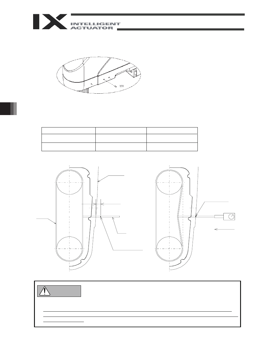
6.3.5 Checking the Belt Tension for the Rotational Axis
(1) Remove one setscrew provided on a side face of arm 2.
Remove the screw at the center.
(2) Insert
a
I3 pin in the hole on the side face of arm 2 (pin length: 40 to 80 mm) until the pin lightly
contacts the belt, and then mark a point off C (mm) from the surface of arm 2.
(3) Using a push-pull gauge, push the pin with a force of D (kgf). The belt tension is normal if the mark on
the pin aligns with the surface of arm 2. If not, adjust the belt tension by referring to 6.3.7, “Adjusting
the Belt Tension for the Rotational Axis.”
Type C
D
IX-NNC50
/60
2.48 (mm)
1.3 ~ 1.5 (kgf)
IX-NNC70
/80
3.60 (mm)
1.6 ~ 2.0 (kgf)
D (kgf)
Pulley
C (mm)
Mark aligns with the
surface of arm 2.
Mark here
Pin
Arm 2
Pulley
Belt
Pulley
z Do not use a pin with a sharp tip that may damage the belt.
z Disassembly of the cover generates dust. Before disassembling the cover, move the robot to a
location where dust will not cause problem, or cover the robot with a plastic sheet, etc., to prevent
dust from scattering.
Caution