2 external dimensions, Ix-nnc50, 71 7. specifi cations – IAI America IX-NNC8040 User Manual
Page 77
71
7. Specifi
cations
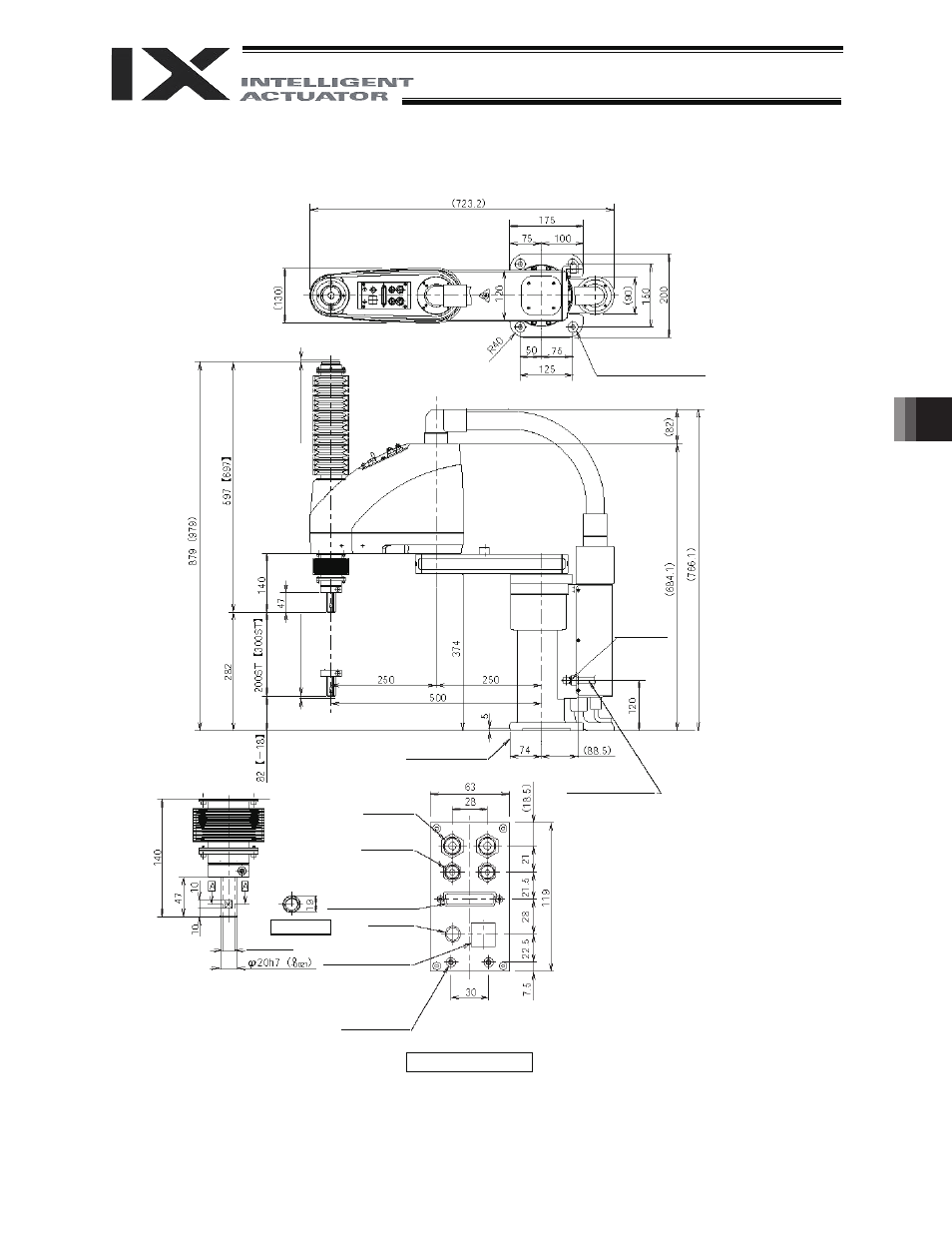
7.2 External
Dimensions
IX-NNC50
4 -
I11 hole
I24 counterbore, depth 5
5 (
M
echa
ni
cal
e
nd)
2-M4
depth 8
(*1)
Air joint
(opposite side)
(*4)
5 (
M
echa
ni
cal
e
nd)
Reference surface
Applicable tube:
Outer diameter
I12
(inner diameter
I8)
I6 quick
air-tube joint
I4 quick
air-tube joint
Red
Yellow
User Connector
D-sub 25-pin connector
for user wiring (socket),
fixing screw M2.6
Black
White
*1: The holes for the 2-M4 screws (depth 8) pierce through the
thickness of the arm’s side wall. If the mounting screws are
long, they will contact the internal parts. Exercise due
caution in this regard.
*2: External force applied to the spacers must not exceed 30 N
in the axial direction or 2 N
m in the rotating direction (for
each spacer).
*3: The LED operates only when the user provides a circuit that
receives controller I/O output signal and supplies 24 VDC to
the LED terminal in the user connector.
*4: The joint can be installed on the opposite side. (To reverse
the direction, swap the PT3/8 plug and the joint.)
ALM (*3)
BK SW
Brake-release switch
I14, hollow
Section A-A
Spacer
Outer diameter
I 7
Height 10 (M4)
Depth 5 (*2)
Detailed view of panel (1/2)