Warning – IAI America IX-NNC8040 User Manual
Page 62
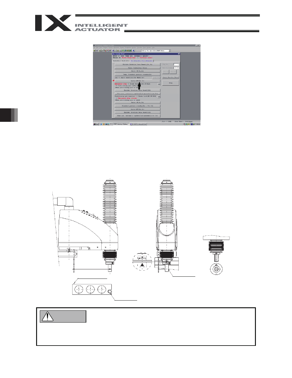
56
6. Inspection/Maintenance
(6)
Click the “Servo-OFF” button.
(7)
Press the emergency-stop switch.
(8)
Affix the rotational axis at the reference position by setting the plate and pin of the adjustment jig as
illustrated below.
x Set the jig after confirming that the emergency-stop switch is pressed.
x Set the jig after adjusting the rotational axis to the reference position, using the positioning mark
label as a guide.
x The top face of the stopper should roughly align with the bottom face of arm 2.
The plate and pin should
make light contact.
D-cut surface
Positioning mark label
for rotational axis
Location of positioning seal
on IX-NNC70
/80
Location of positioning seal
on IX-NNC50
/60
D-cut surface
z Always press the emergency-stop switch before setting an adjustment jig. Failure to do so may
cause the robot to malfunction and result in a serious accident.
z Pay attention to the orientation of the D-cut surface of the plate jig.
Warning