Caution, 2 removing the cover – IAI America IX-NNC8040 User Manual
Page 44
38
6. Inspection/Maintenance
6.3.2 Removing the Cover
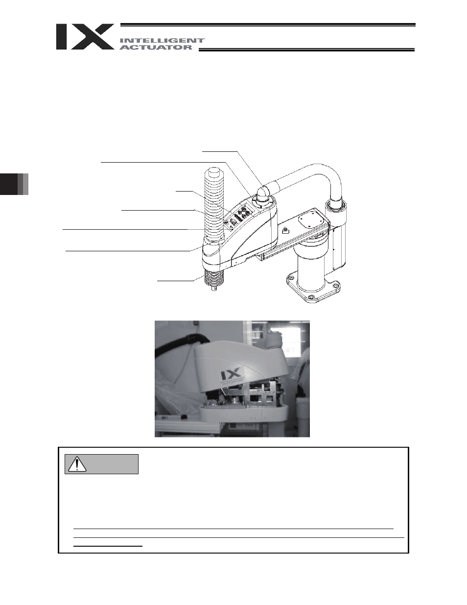
(1) With arms 1 and 2 extended as illustrated below, press the brake-release switch [1] to release the
brake and then push down the vertical axis until the stopper contacts the pulley.
(2) Remove the countersunk head screws [2], [3] and [4] (four pieces each), in that order.
(3) Remove all connectors (UA, UB, BK and LED) and air tubes (four pieces) from the back of the panel.
(4) Move the cover to the position shown in the photograph.
Rotary joint
[4] 4 - M3 x 12 (countersunk head screw)
Panel
[1] Brake-release switch
[2] 4 - M3 x 12 (countersunk head screw)
[3] 4 - M3 x 12 (countersunk head screw)
Vertical axis
z Remove the four outer screws for the countersunk head screws [4].
z Do not remove the M/PG connectors at the rotary joint, since it will necessitate an absolute reset.
z The cover will not detach completely, since the M/PG connectors are still connected. Do not pull
the cover forcibly.
z Disassembly of the cover generates dust. Before disassembling the cover, move the robot to a
location where dust will not cause problem, or cover the robot with a plastic sheet, etc., to prevent
dust from scattering.
Caution