IAI America IX-NNN12040 User Manual
Page 42
2. Installation
36
x
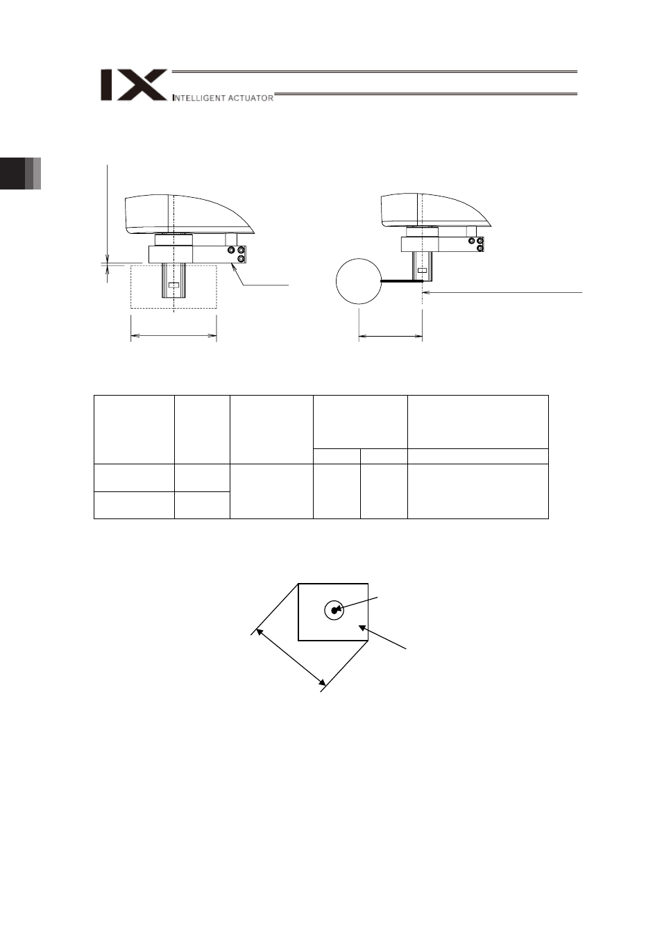
For the attachment of the load, make sure to keep it below the allowable load diameter,
load offset, transportable weight and allowable moment of inertia.
Revolution Center of Rotation Axis
Load Diameter φK
70mm or less
Bracket L
Clearance 1.2mm Min.
Center
of Grevity
Load
Transported
Weight [kg]
Rotation Axis
Allowable Moment of
Inertia
[kg㨯m
2
]
Model
Number
Load
Diameter
K
(Note)
[mm]
Center of
Gravity
Load(positions
of centers)
and Offset
Rated
Max.
Rated and Maximum
IX-NNN10040
90
IX-NNN12040
240
70mm or less
[See the
next page]
20
50
0.5
(Note)
Load diameter is determined by the furthest point from the revolution center. For
example, if the load is in a rectangular shape, the tool diameter is a diagonal line as
shown in the figure below.
(Note) Ɣ In case the load diameter exceeds the value specified in the table, the tool will
interfere with the base part. Use it by changing the operation restriction and the
values in the software limitation for J2-axis. [Refer to 1.2.2 [2]. Operation
Restriction]
Also, make sure to use within the allowable range for the moment of inertia for the
load.
Ɣ Have at least 1.2mm or more for the clearance between the load and Bracket L.
Load Diameter
Load Offset
Center of Rotation Axis
Tool Diameter
Load