IAI America IX-NNN12040 User Manual
Page 27
1. Specifications Check
21
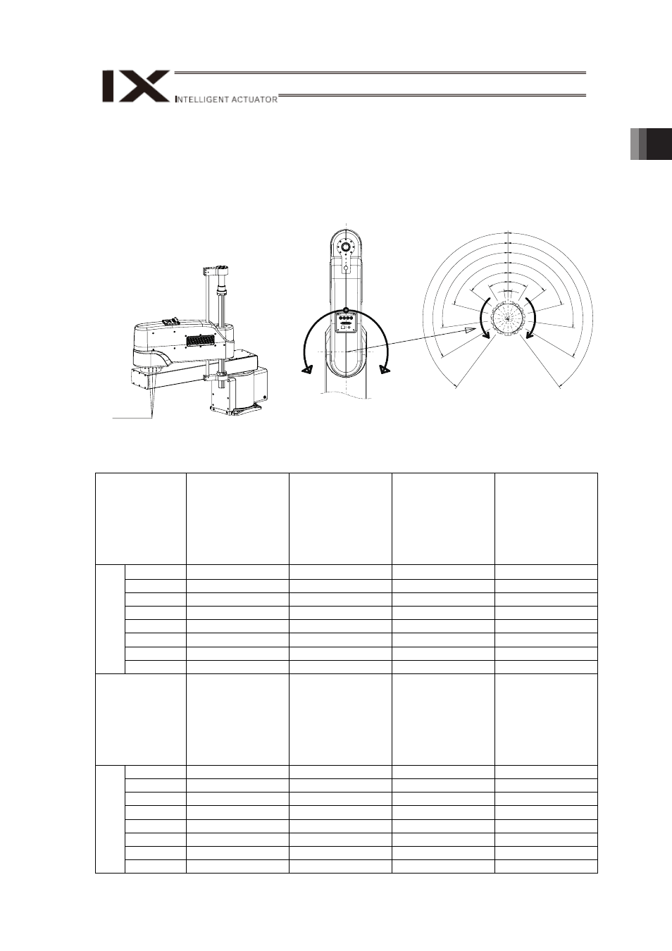
(2) J2-Axis Operation Restriction Angles
J2-axis of the angles of the mechanical ends, angles of the operation restrictions and the
parameters are as shown in the figures and table below.
When limiting the moveable angle, attach the M8x15 hex socket head screw for movement
limitation to an M8 tapped hole for J2-axis rotational limitation and change the soft limit, and
then acquire the stopper position and conduct the stopper push type absolute reset.
J2-Axis Operation Restriction Angles and Parameters
No.
Angle of Stopper
Position (ME)
[degree]
Angle of Software
Limitation
[degree]
Angle from
Software
Limitation to ME
[degree]
Software
Limitation
Parameter (Each
Axis Parameter
No. 7 Software
Limitation +
J2-Axis)
1
8.0
-2.0
10
-2000
2
30.5
20.5
10
20500
3
53.0
43.0
10
43000
4
75.5
65.5
10
65500
5
98.0
88.0
10
88000
6
120.5
110.5
10
110500
7
143.0
133.0
10
133000
P
os
iti
ve
D
ire
ct
io
n
of
C
oo
rd
in
at
e
Default
160.0
150.0
10
150000
No.
Angle of Stopper
Position (ME)
[degree]
Angle of Software
Limitation
[degree]
Angle from
Software
Limitation to ME
[degree]
Software
Limitation
Parameter (Each
Axis Parameter
No. 7 Software
Limitation -
J2-Axis)
1
-8.0
2.0
10
2000
2
-30.5
-20.5
10
-20500
3
-53.0
-43.0
10
-43000
4
-75.5
-65.5
10
-65500
5
-98.0
-88.0
10
-88000
6
-120.5
-110.5
10
-110500
7
-143.0
-133.0
10
-133000
Neg
ative
Dire
ction
of
C
oo
rd
in
at
e
Default
-160.0
-150.0
10
-150000
J2-Axis M8
Tapped Holes
for Rotational
Restriction
1
2
3
4
5
6
7
8
9
10
11
12
13
14
Negative
Direction
Negative
Direction
Positive
Direction
Positive
Direction
Mechanical end angles from the top view of
J2-axis with M8 hex socket head screws for rotational
restriction allocated (operation available on the side of
rotational restriction screws)