3 flange (option model: ix-fl-5), Specifications check 27 – IAI America IX-NNN12040 User Manual
Page 33
1. Specifications Check
27
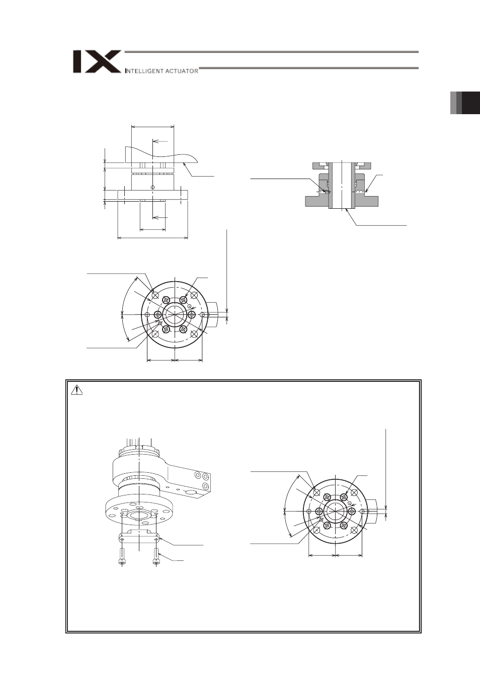
1.3 Flange (Option Model: IX-FL-5)
It is the flange to be used when attaching a load on the tip of the vertical axis arm.
A
A
φ
68
φ
110
(7.2)
(35)
15
3
φ
40 h7
0
-0.025
Bracket
C
4-φ11 Through Hole
2-M6, Depth 12
φ90
φ56
45
°
45
±0.03
2-
φ8 H7
Through Hole
+0.015 0
45
±0.03
30
°
Tapped hole for
detaching flange
B
Hex Socket Set Screw
Ball Spline Shaft
Caution:
1. Vertical axis flange option is held on with a locking assembly. To remove the flange, it is
necessary either to loosen the screws in Part C, or to use an equivalent tool (e.g.
pulley dismantler) to pull it out. Do not attempt to put impact on the flange to remove it.
2. The tightening torque for the screws (M6) in Area C is 12.3N•m. Do not tighten the
screws with the specified torque at once. Tighten the screws with half of the specified
torque temporarily, first, and then tighten again with the specified torque afterwards.
Also, always tighten the screws diagonally.
The tightening torque for M6u6 hex socket set screws is 5.9N•m.
C
4-φ11 Through Hole
2-M6, Depth 12
φ90
φ56
45
°
45
±0.03
2-
φ8 H7
Through Hole
+0.015 0
45
±0.03
30
°
Tapped hole for
detaching flange
M6×6
Bumping Hood
Optional flange
dismantling tool