IAI America IX-NNN12040 User Manual
Page 41
2. Installation
35
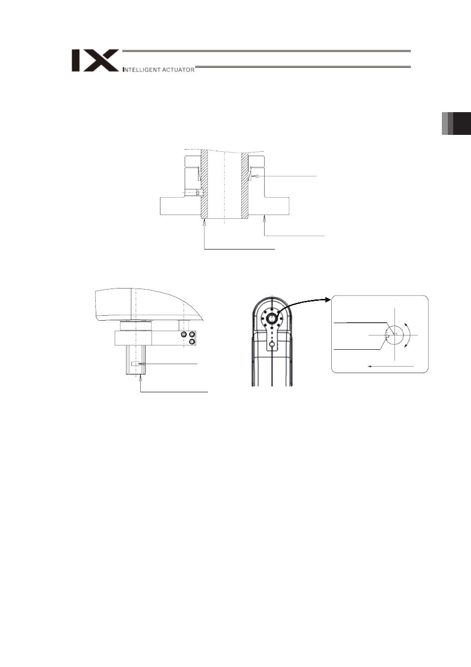
[2] Attachment of the load
x
To attach the load, use a bracket with tightening force that possesses enough strength
and stiffness, and would not slip.
Shown in the figure below is an example of attachment when the optional flange is used.
Please take this as a reference.
Shrink Discs
Flange (Option)
Splined Ball Screw
x
Utilize the D-shaped flat face on the tip of rotation axis for positioning (in rotational
direction) of rotation axis.
0°
-X
-R
+R
0°
Rotation axis
D-cut surface
Center of tool
attachment surface
Rotation axis position from top view
D-Cut Surface
Splined Ball Screw
(Note) The D-cut surface is not for attachment purpose. Do not attempt to hold a bolt or set
screw against this surface to fix a load. Use such tools as split cramp or locking
assemblies to mount a load.