2 installation surface – IAI America LSAS-N15HM User Manual
Page 50
9. Installation
34
Reference
surface
Reference
surface
Reference
surface
Reference
surface
Reference
surface
Reference
surface
z166160
z1661601+61+0
z166160
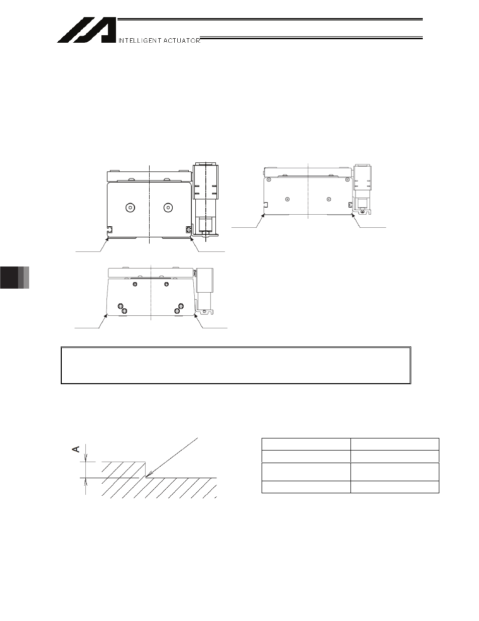
9.2 Installation
Surface
x Ensure
that
the frame offers sufficient structural rigidity to prevent generation of vibration.
x Install the actuator on a machined surface or other flat surface of equivalent accuracy. The flatness of
the
installation
surface must be 0.05 mm or less.
x Provide sufficient space to allow for maintenance work.
x The
side
and bottom surfaces of the actuator base provide reference surfaces used for alignment of
slider travel.
x If you require higher traveling accuracy, install the actuator using these reference surfaces.
Caution: As shown above, each side surface of the base provides a reference surface used for
alignment of slider travel. If you require higher traveling accuracy, therefore, install the
actuator with reference to either side surface of the base.
When installing the actuator on the frame using the base reference surfaces, provide the necessary
machining by following the drawing below.
Model
Dimension A
N10SS, N10SM
2 to 3.5
N15SS, N15SM,
N15HS, N15HM
2 to 3.5
N19SS, N19SM
2.5 to 4
R0.3 or less