1 installing the actuator – IAI America LSAS-N15HM User Manual
Page 47
9. Installation
31
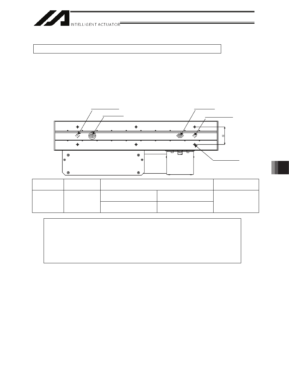
Reamed hole
Reamed hole
Long hole
Long hole
Tapped hole
9.1 Installing
the
Actuator
Install the actuator on a machined surface or other flat surface of equivalent accuracy.
9.1.1 N10SS,
N10SM
Mounting tapped holes are provided on the back of the base. Use these tapped holes for mounting the
actuator. The effective depth of the screws for mounting the base is as shown below. Because the taps
are blind holes, exercise due caution when selecting the bolt length.
If an inappropriate bolt is used, the tapped holes may be damaged and/or the mounting strength of the
actuator may become insufficient, causing the degradation of precision and/or unexpected accidents.
Additionally, the reamed holes for the positioning pins are provided on the back of the base.
Tap diameter
Effective tap
length
Tightening torque
Reamed hole
Bolt bearing surface is
steel
Bolt bearing surface is
aluminum
M6 12
mm
12.4 N
ym (1.26 kgfym) 5.36
N
ym (0.55 kgfym)
10H7 depth 8 mm
About Tightening Screws
x Use hexagonal socket head bolts for the male screws used to install the base.
x Use of high-strength bolts of ISO-10.9 or greater is recommended.
x Ensure at least the following effective thread lengths for the bolts and male screws:
Male screw is made of steel
o Same as the nominal diameter
Male screw is made of aluminum
o Twice the nominal diameter