IAI America ZR-M User Manual
Page 55
41
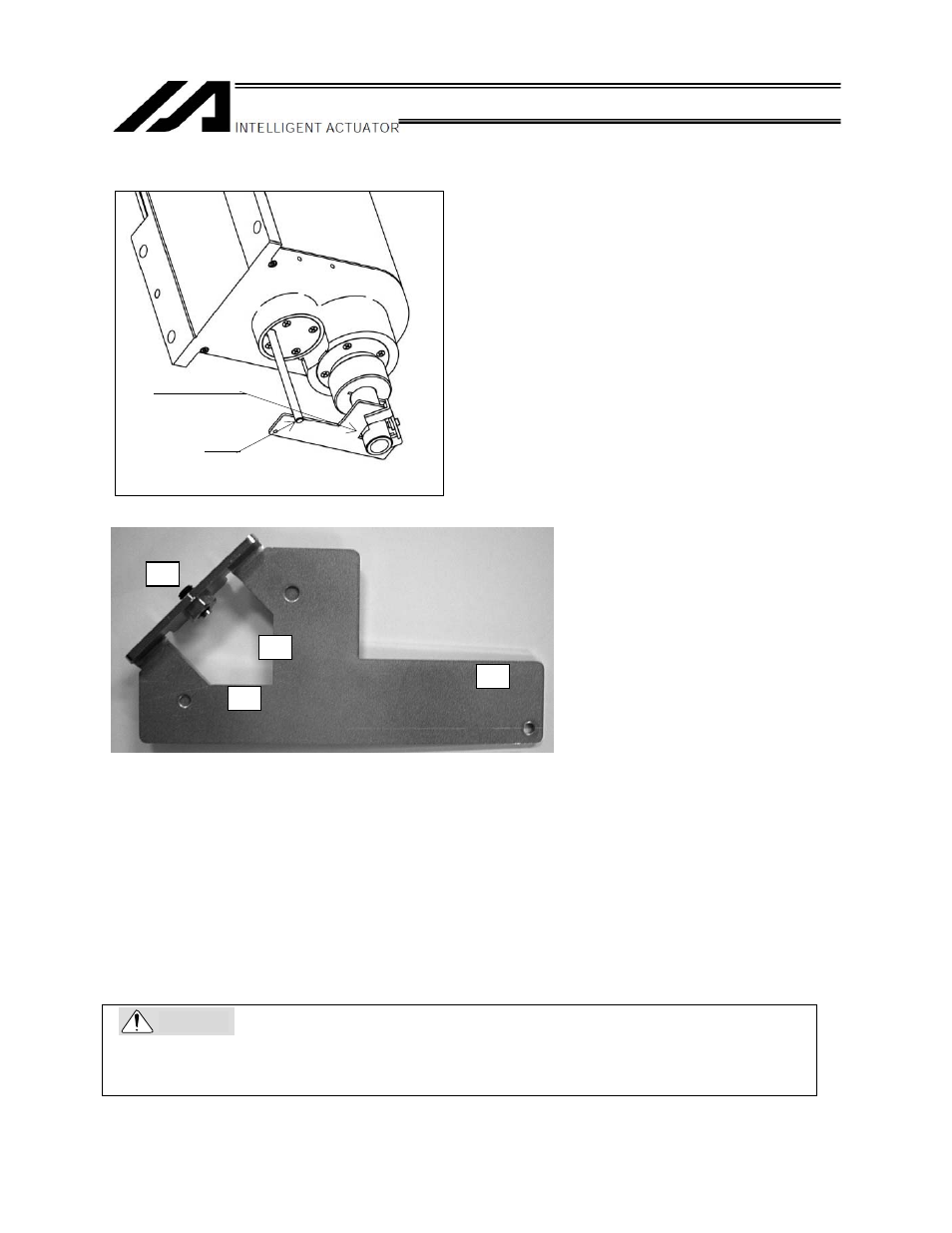
(12) Set the plate and pin constituting the adjustment jig as shown below to affix the axis in the reference
position.
Installation method
[1] Insert the ball screw spline into the hole in the jig from below.
[2] Cause the D-cut surface of the ball screw spline to contact surface a.
[3] Cause the side face of the ball screw spline to surface b.
[4] Tighten screw c to affix the jig on the ball screw spline.
* At this time, confirm that the adjustment jig is vertical to the ball screw spline and that the D-cut
surface and surface a are in close contact with each other.
* Applicable screw: Hexagonal socket head screw M5
* Tightening torque: 20 [N
cm] (Reference)
[5] Insert the supplied shaft into the hole in the ZR unit.
* Keep holding the shaft, because the shaft will drop once you release your hand.
[6] Turn the ball screw spline until the supplied shaft lightly contact surface d of the jig.
Be sure to press the emergency stop switch before setting the adjustment jig. If not, the robot may
malfunction and a serious accident causing injury or death may occur.
Warning
c
a
d
b
D-cut surface
Shaft
a
b
c
d