3 wiring method, Wiring method – IAI America ZR-M User Manual
Page 36
22
10.3 Wiring Method
(1) Determine the control axis number (Axis No.) of each actuator according to the system (program)
and connect the actuator to the corresponding connector on the controller.
Encoder cable connector
Motor cable connector
Control axis number
(Axis No.)
Display on
controller front
panel
Control axis number
(Axis No.)
Display on
controller front
panel
1 PG1
1 M1
2 PG2
2 M2
3 PG3
3 M3
4 PG4
4 M4
5 PG5
5 M5
6 PG6
6 M6
Caution: If connector numbers are not shown on the cables, mark the connector numbers or other
identification information on the cables to prevent mis-wiring during maintenance. Wrong
connections may result in damage or malfunction of the motor/board.
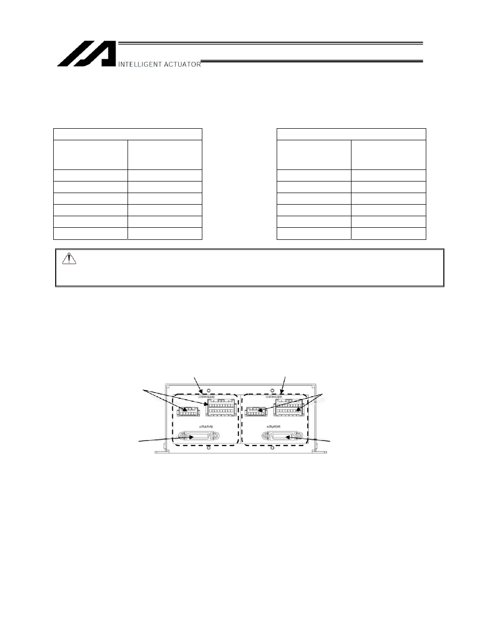
(2) Both the left and right brake boxes are connected to one axis, respectively.
The Z-axis and R-axis encoder cables can be connected to either side, but certain rules apply. If the
Z-axis is connected to the connector (ACTUATOR2) on the left box, for example, the cable
connecting the left brake box and XSEL controller should be the one whose axis number
corresponds to the Z-axis on the X-SEL side, and accordingly this cable should be connected to the
applicable connector (CONTROLLER2).
CONTROLLER2
Controller
connectors
ACTUATOR2
ZR unit connector
Left side
Right side
CONTROLLER1
Controller
connectors
ACTUATOR1
ZR unit connector