3 installation of tool and load, Installation of tool and load – IAI America ZR-M User Manual
Page 31
17
9.3 Installation of Tool and Load
(1) Installing
the
tool
The tool mounting part must have sufficient strength and rigidity, along with adequate fastening power to
prevent positional shift.
It is recommended that a tool be installed over a split ring, power lock or other appropriate part.
(The flanges specified in 4, "Options" are available.)
To set the rotating direction using the D-cut surface and setscrews, be sure to use setscrews with resin
or brass pad or set pieces made of soft material.
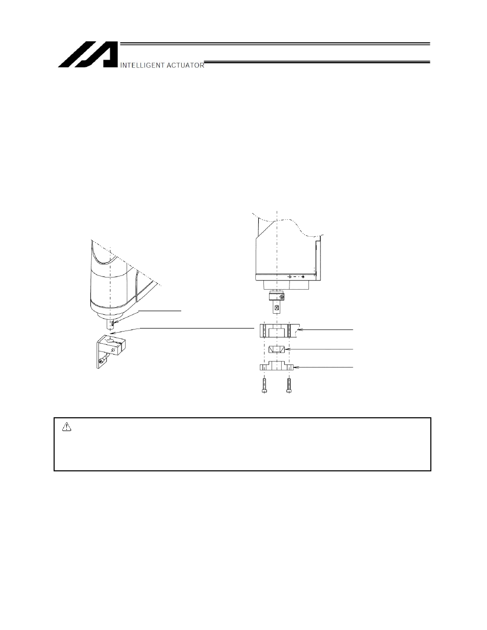
An example of installation is shown below for your reference.
Caution: Use the D-cut surface at the tip of the R-axis (rotational axis) to position the R-axis.
Avoid attachment of the tool at the D-cut surface via thread fastening. Doing so may
damage the D-cut positioning surface.
Design the tool so that it will not contact any device that secures the ZR unit.
D-cut surface
R-axis (Center of the rotational axis)
Tool
Power lock
Pressure flange