Names of the parts – IAI America ZR-M User Manual
Page 15
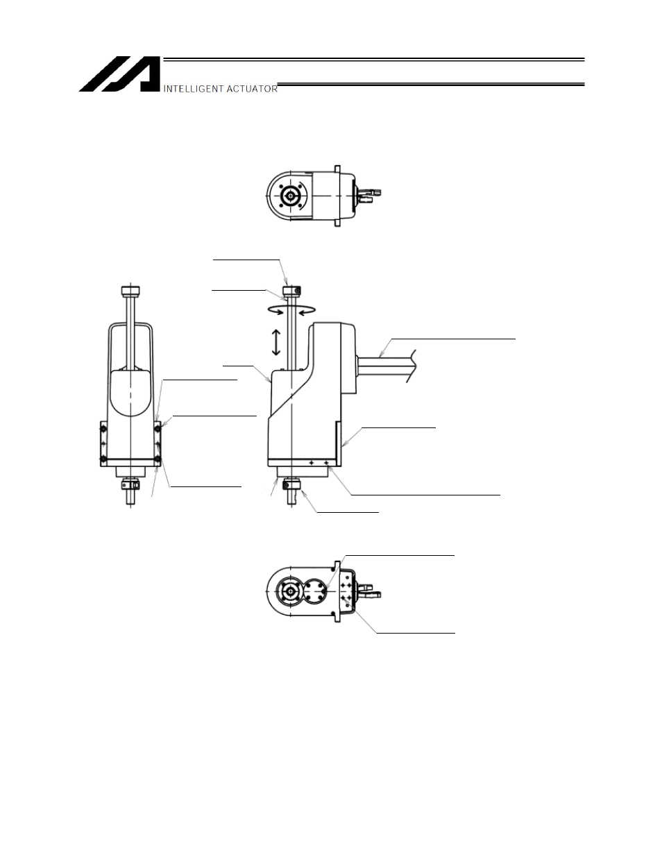
1
1.
Names of the Parts
* For the detailed dimensions, refer to 2, "External Dimensions."
Base
Tapped holes for installing user
components
(Tap size: M4 x 12 on both sides)
Connector box
Mounting hole, 4 locations
Tap size: M5 x 8
Mounting flange
Mounting flange
Mounting hole
4 locations, tap size
ZRS: M6, ZRM: M8
Positioning pin hole
2 locations
Hole diameter
6H7
(+0.012)
ZR-S: 7 mm from back side
ZR-M: 8 mm from back side
* Not a through hole
Base
Z-axis stopper
Ball screw
spline shaft
R-axis (Rotational axis)
Z-axis
(Vertical axis)
Cover
Z-axis, R-axis
(Motor cable, encoder cable)
Z-axis stopper
Positioning pin hole for ball
screw spline adjustment
This manual is related to the following products: