Section 5: serial communication wiring, Jp3 jumper configuration, Tb4 wiring connections – Fairbanks PC2250 Utility Software User Manual
Page 27
6/12
27
51214 Rev. 7
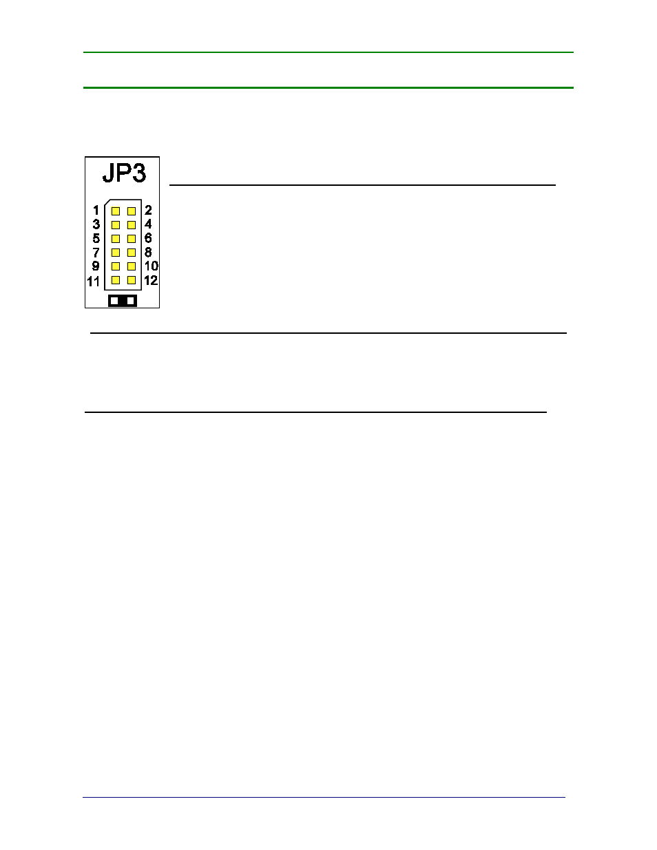
Section 5: Serial Communication Wiring
JP3 Jumper Configuration:
JP3
RS232
RS485
RS422*
Port
1-2
out
120
Ω resistor 120 Ω resistor Com1
3-4
out
in
out
Com1
5-6
out
in
out
Com1
7-8
out
in
out
Com2
9-10
out
in
out
Com2
11-12
out
120
Ω resistor 120 Ω resistor Com2
120 ohm termination resistors required if the receiver is the last node of the network
TB4 Wiring connections
RS232
RS485
RS422*
Port #
TB4 (A)
1
Rx Receive Data
RS485 -
RS422 Rx -
Com 1
2
Tx Transmit Data
RS485 -
RS422 Tx -
Com 1
3
CTS Clear to Send
RS485 +
RS422 Rx +
Com 1
4
GND
GND
GND
Com 1
5
RTS Ready to Send
RS485 +
RS422 Tx +
Com 1
TB4 (B)
1
Rx Receive Data
RS485 -
RS422 Rx -
Com 2
2
Tx Transmit Data
RS485 -
RS422 Tx -
Com 2
3
CTS Clear to Send
RS485 +
RS422 Rx +
Com 2
4
GND
GND
GND
Com 2
5
RTS Ready to Send
RS485 +
RS422 Tx +
Com 2
TB4 (C)
1
Tx + Passive 20 mA Output
Com 2
2
Tx – Passive 20 mA Output
Com 2
3
+7.5 V Bluetooth® Technology Supply
*Port should be set to RS485.