Model jb1 - sizing and application data, Essential ordering information and data – Fulton VMP Webster Oil_Combo Burner User Manual
Page 6
(1)
STANDARD UL EQUIPMENT
AND IMPORTANT OPTIONS
Fuel Burned
STANDARD UL EQUIPMENT
AND IMPORTANT OPTIONS
Fuel Burned
Gas
No. 2 Oil pressure atomized
Gas
No. 2 Oil pressure atomized
General
Motor, Fan and Air Inlet Control
X
X
Gas Fuel
Main Manual Shutoff Valve
X
Air Flow Switch (also with oil sys-
tems using remote pump)
X
Main Safety Shutoff Valve
X
(2)
Burner Mounted Control Panel,
Switch and Indicator Lights
X
X
Second Safety Shutoff Valve
X
Flame Safety Control
X
X
Main Gas Regulator
X
Ultra Violet Scanner
X
X
Gas Checking Valve
X
Motor Controller (single phase
voltage)
X
X
High and Low Gas Pressure
Switches (st’d over 2500 MBH)
Opt.
Fuel Selector Switch
Duel Fuel Burners Only
Metering Valve (modulation only)
X
Ignition
Proven Gas Pilot Ignition
X
Oil Fuel
Oil Drawer Assembly with Diffuser
X
Pilot Solenoid Gas Valve
X
Oil Nozzle(s)
X
Pilot Gas Regulator & Manual Valve
X
Integral Oil Pump
X
Pilot Gas Ignition Transformer
X
Main Safety Shutoff Valve
X
Direct Spark Oil Ignition
X
Second Safety Shutoff Valve
X
Direct Spark Oil Ignition
Transformer
X
Low Oil Pressure Switch
(STD when using remote oil pump)
Opt.
Optional
Inverted Housing
X
X
Oil Pressure Gauge
X
Alternate Control Cabinet
Positioning
X
X
Oil Metering Valve (modulating
systems)
X
Remote Control Panel
X
X
Future Gas Combustion Head-OPT
Opt.
Fuel Metering CAM-NETIC II
X
X
1. The configuration of each unit will vary with specific job requirements such as input rating, electrical specification and special agency approval
codes. The above chart shows those items standard to a basic burner plus a few options that may be added.
2. Indicator lights are “Power On”, “Call for Heat”, ”Fuel On” and ”Flame Fail” for hard wired panels. “Alarm”, “Low Water”, “Power”, “Call for
Heat”, “Ignition On”, and “Fuel On” for circuit board light panels.
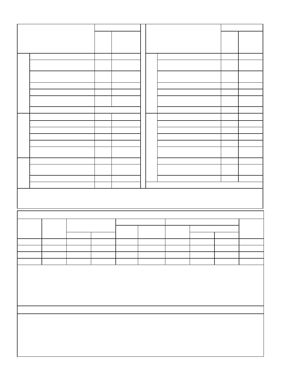
Model JB1 - Sizing and Application Data
(contact Webster for complete information)
Model
Number
Maximum
Furnace
Pressure
Burner Firing Capability
Range
Burner Motor HP
Gas Train
Oil Pump
Motor HP
Gas Only
HP
(3)
Oil or
Combination
Pipe Size
(4)
Inlet Pressure
Gas scfh
#2 Oil gph
On-Off, LFS
Modulation
JB1-02
1.25
400 / 1000
3.0 / 7.1
1/4
1/3
1”
6 / 14”
7 /14”
Integral
JB1-03
1.25
600 / 1500
4.0 / 10.7
1/3
1/2
1 1/4”
8 / 14”
9 / 14”
Integral
JB1-05
1.25
800 / 2100
6.0 / 14.8
1/2
1/2
1 1/2”
7 / 14”
8 / 14”
Integral
JB1-07
1.25
900 / 2500
7.0 / 17.8
3/4
3/4
1 1/2”
9 / 14”
11 / 14”
Integral
3. Larger motors may be required for single phase or 208 volts 4. Contact Webster for more complete details
The above maximum ratings are based on 0 furnace pressure, an altitude of 1000 feet, 90oF air temperature and 60 HZ electrical supply. Use
the following corrections for higher temperatures and altitude. Capacity decreases by 17% for 50 Hertz.
Capacity decreases by 4% for each 1000 feet above 1000 foot altitude.
Capacity decreases by 6% for each 1 inch of furnace pressure.
Capacity decreases by 2% for each 10
o
F increase in air temperature over 90
o
F.
Gas input ratings based on 1000 BTU/cu ft. and 0.64 specific gravity. Sizes and pressure will vary with gas.
Oil input ratings are based on 140,000 BTU/gal for ASTM #2 fuel oil.
Essential Ordering Information and Data:
Power Supply - Confirm 120-60-1 for control circuit and electrical supply for burner motor(s) (voltage, frequency and phase).
Describe Boiler or Heater to be Fired - Including the manufacturer, model number, furnace pressure and furnace size.
Firing Rate - Define firing rates in MBH for gas and GPH for oil.
Fuel to be Burned - Type of gas and/or oil, including the BTU value.
Approval Agency - UL, FM, IRI (GE GAP), CSD-1, NFPA, Mil spec and local codes, if applicable.
Flame Safety Control Preferred - Honeywell or Fireye controls.
Gas Train Components Preferred - ASCO/ITT, Honeywell or Landis
Control System - ON-OFF, Low Fire Start, Low-High-Low, Modulation, Posi-Control
Required Options - Mounting plate, limit controls, etc.
Model JB1 - Specification Data (400 - 2500 MBH Input)
Page 6
Specification
JB Manual