Figure b-4 control panel circuit board design, Figure b-5 control panel hard wired design, Figure b-6 air compressor – Fulton VMP Webster Oil_Combo Burner User Manual
Page 13
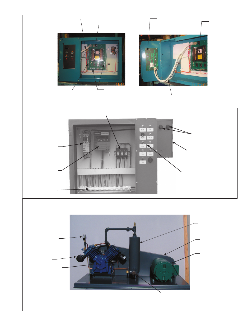
Panel Wiring
Terminal Strip
Switch / Light
Panel
Combination Flame
SafeGuard Base
and Circuit Board
Field Wiring
Terminal Strips
Board to Light
Panel Cable
Light Panel
Circuit Board
Flame SafeGuard
Base
Board to Light
Panel Cable
Figure B-4
Control Panel
Circuit Board
Design
Electrical Panel Identification: The above pictures show the flame safeguard base mounted on a circuit board. Connections are wired via cable to
light / switch circuit board. Picture below shows the flame safeguard (base) mounted directly to the panel back plate.
Terminal Strip
Control Transformer
Transformer Fuses
Flame Safeguard
Burner Motor
Starter
Control Relays
Switch / Light Panel
Figure B-5
Control Panel
Hard Wired
Design
Page 13
Identification
JB Manual
Electric Motor
Belt Guard
Air Chamber
Air Discharge
Connection
Compressor
Air Filter
Pressure
Gauge
Figure B-6
Air Compressor