E. burner mounting criteria – Fulton VMP Webster Oil_Combo Burner User Manual
Page 19
Page 19
Burner Mounting Criteria
JB Manual
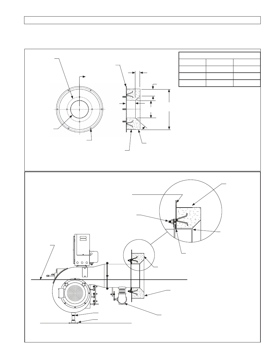
E. BURNER MOUNTING CRITERIA
It is of vital importance that the burner be properly mounted to the boiler or appliance being fired. Improper mounting
can cause leakage of the hot gases back around the burner head resulting in warpage and deterioration. The following
illustrations show the proper way the burner must be installed to validate warranty conditions.
TYPICAL JB1, 2, 3 BURNER REFRACTORY FRONTPLATE
B
- Bolt Circle
A
- Opening
Minimum of six (6) holes for
boiler mtg. studs, 1/2” or larger
Minimum 7 gauge
Dimensions - Inches
MODEL
DIM. A
DIM. B
JB1
7 5/8
10 3/4
JB2
9 5/8
12 3/4
JB3
11 5/8
14 3/4
4”
30
o
to 45
o
taper,
see note 4
2” Minimum
2” Minimum
A
Minimum 14 Gauge
A
See Note 3
Use minimum
of four (4) 1/2”
studs with lugs.
Refractory OD is sized to fit
vessel opening with 1/4” to
1/2” gap, Refractory must
extend 2” beyond tube
sheet for scotch boilers.
Figure E-1
Refractory Dimension
Note: For JB burners equipped
with a low NOx cone, refer to ad-
dendum number 950064
Contact Webster for more detailed
refractory drawings
The burner must
be level
Pipe support required
Flange secured to floor
The gas piping from the burner to the
train should have as few elbows as pos-
sible to reduce presure drop.
Attachment to vessel varies with manu-
facturer (follow vessel manufacturers
recommendation.
If gap is over 3/16”,
wrap burner nose
with high tempera-
ture ceramic insulat-
ing rope.
Tighten clamp bolts
uniformly - check after
firing for several hours
Fiberglas rope
gasket must be
coiled to cover
the full mounting
flange surface
This surface must be
sealed against the vessel.
Check vessel mounting
requirements
Fill voids be-
tween front plate
and vessel with
ceramic blanket
4” deep or as
defined by vessel
manufacturer.
Refractory
Front Plate
Figure E-2
Burner Mounting Instruction