Gas systems – Fulton VMP Webster Oil_Combo Burner User Manual
Page 23
3. Gas Systems
Illustrated Gas Trains by Capacity and Code: The following illustrations show the Webster configuration for UL,
FM and IRI as grouped by UL capacity ratings. Refer to the legend below for component part identification. These
illustrations are not to be used for field erection and/or system design purposes.
Page 23
Fuel Systems
JB Manual
UL Capacity Range
BTU/Hr.
Operation Mode
Webster
Designation
Code
Illustration
UL / GE
GAP
FM
To 2,500,000
On-Off
A
X
X
722091
Low Fire Start
L
X
X
722001
Low Hi Low
H
X
X
722022
Modulating
M
X
X
722003
2,500,001
to
5,000,000
Low Fire Start
L
X
722002
Low Fire Start
L
X
722009
Low Hi Low
H
X
722023
Low Hi Low
H
X
722024
Modulating
M
X
722004
Modulation
M
X
722010
5,000,001
to 12,500,000
Modulating
M
X
722005
Modulating
M
X
722011
12,500,001
and Up
Modulating
M
X
722082
Modulating
M
X
722084
NOTE: Pressure Drops; Pressure drop through a given gas train will vary somewhat in relation to the individual items
used, the specific gravity of the gas to be burned and the overall length.
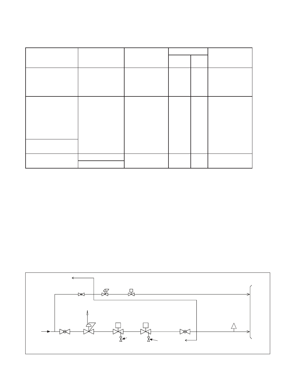
Field Piped
Pilot Manual
Ball Valve
Pilot Gas
Pressure
Regulator
Pilot Solenoid
Valve
Gas Pilot
Ignitor
Gas Burner
Manifold
Manual Ball
Valve
Manual Ball
Valve
Vent To Outside
Atmosphere
Manual
Test Valve
Gas
Supply
UL-FM On-Off Gas Piping Diagram - Up to 2,500 MBH Firing Rate 1/2 PSI Max
Manual Test
Valve
S
S
Test
Connection
Gas Pressure
Regulator
Main Diaphragm
Gas Valve
Main Solenoid
Gas Valve
D
Field Piped
722091
722091