Table of contents a. introduction, Figure a-1 nameplate – Fulton VMP Webster Oil_Combo Burner User Manual
Page 3
Safety Precautions ...............................................................................................................................
A.
Introduction ..........................................................................................................................................
Burner Model Number .............................................................................................................
JB1 Specifications ...................................................................................................................
JB2 Specifications ...................................................................................................................
JB3 Specifications ...................................................................................................................
B.
Component ldentification ......................................................................................................................
C.
Installation ............................................................................................................................................
D.
Special lnstructions For Canadian lnstallations .....................................................................................
E.
Burner Mounting Criteria ......................................................................................................................
F.
Fuel Systems ........................................................................................................................................
G.
Initial Settings .......................................................................................................................................
H.
Ignition Systems .................................................................................................................................
I.
Start-up & Operating Adjustments .......................................................................................................
J.
Trouble Shooting ..................................................................................................................................
K.
General Maintenance and Care ...........................................................................................................
L.
Care of The Burner During Extended Shutdown ..................................................................................
M.
Replacement Parts ..............................................................................................................................
N.
Warranty Validation & Field Start-up Report ........................................................................................
Start-Up Report .......................................................................................................................
2
3
5
6
8
10
12
17
18
19
20
28
30
32
42
45
48
48
48
49
TABLE OF CONTENTS
A. INTRODUCTION
Page 3
Introduction
JB Manual
This manual covers the Models JB1, JB2 and JB3 CYCLO-
NETIC burners offered by Webster Engineering & Manu-
facturing Co., LLC. These burners can be used in a wide
variety of Cast Iron, Firebox, Firetube, Flextube and other
applications. They can fire gas, oil and combination gas
and oil with several different operating systems.
READ AND SAVE THESE INSTRUCTIONS FOR REFER-
ENCE
WARNING
DO NOT ATTEMPT TO START, ADJUST OR MAIN-
TAIN THIS BURNER WITHOUT PROPER TRAINING
OR EXPERIENCE. FAILURE TO USE KNOWLEDGE-
ABLE TECHNICIANS CAN RESULT IN EQUIPMENT
DAMAGE, PERSONAL INJURY OR DEATH.
The startup and maintenance of the JB burner requires the
skills of an experienced and properly trained burner techni-
cian. Inexperienced individuals should not attempt to start
or adjust this burner.
Every attempt has been made to accurately reflect the
burner construction, however, product upgrades and spe-
cial order requirements may result in differences between
the content of this manual and the actual equipment.
These special components will be described in the infor-
mation provided with the burner and should be used as the
controlling document.
NOTE: This manual must be readily available to all op-
erators and maintained in legible condition.
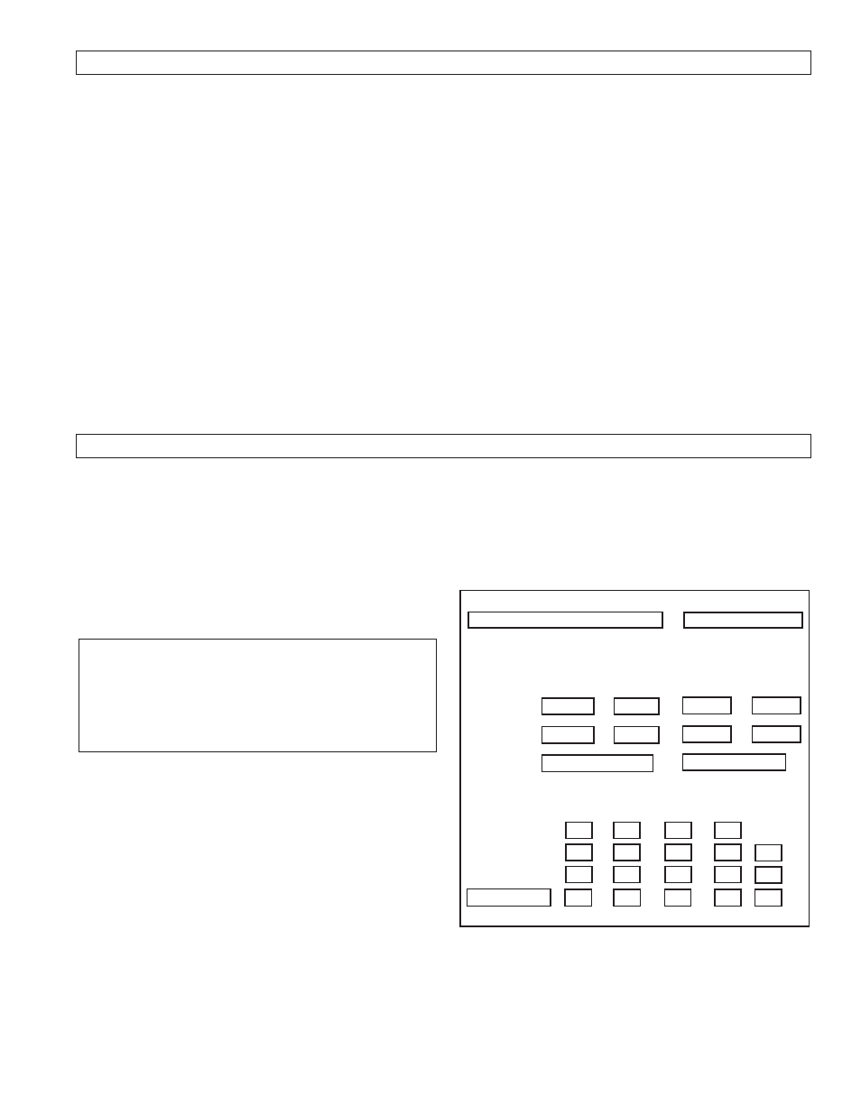
1. Nameplate Information
Each burner has a nameplate with important job details,
similar to the nameplates shown in Figure A-1. An
“X” in the model number refers to a low NOx burner,
where FGR or a NOx cone is used to reduce the NOx
in the combustion gases. If the burner is not a low NOx
burner, there is no “X” in the model.
Figure A-1 Nameplate
MODEL NUMBER
JB2C-15-RM7840L-UL-IRI
SERIAL NUMBER
U81375A-018-06
OIL INPUT RATING
GAS INPUT RATING
MBTU/HR
IN.WC
GPH
PSI
2940
2.8
21
300
MAXIMUM
1680
1.0
12
100
MINIMUM
NATURAL GAS
#2 FUEL OIL
FUEL
VOLTS
AMPS
HERTZ
PHASE
HP
115
CONTROL CIRCUIT
5.0
60
1
208
BURNER MOTOR
5.9
60
3
1.5
208
OIL PUMP MOTOR
4.3
60
3
1/2
The serial number represents the unique number for that
burner and is a critical number that will be needed for any
communications with Webster Engineering.
The input rates define the maximum and minimum inputs
for that burner, given in MBH for gas and GPH for oil. Air
atomized burners show both the oil pressure and air pres-
sure. Pressure atomized burners only list the oil pres-